LM2574N-5G ON Semiconductor, LM2574N-5G Datasheet - Page 10
LM2574N-5G
Manufacturer Part Number
LM2574N-5G
Description
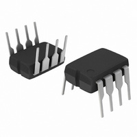
IC REG SW 0.5A 5V STEPDOWN 8-DIP
Manufacturer
ON Semiconductor
Type
Step-Down (Buck)r
Datasheet
1.LM2574N-3.3G.pdf
(26 pages)
Specifications of LM2574N-5G
Internal Switch(s)
Yes
Synchronous Rectifier
No
Number Of Outputs
1
Voltage - Output
5V
Current - Output
500mA
Frequency - Switching
52kHz
Voltage - Input
4.75 ~ 40 V
Operating Temperature
-40°C ~ 125°C
Mounting Type
Through Hole
Package / Case
8-DIP (0.300", 7.62mm)
Output Voltage
5 V
Output Current
0.5 A
Input Voltage
4.75 V to 40 V
Switching Frequency
52 KHz
Operating Temperature Range
- 40 C to + 125 C
Mounting Style
Through Hole
Duty Cycle (max)
98 %
Primary Input Voltage
12V
No. Of Outputs
1
No. Of Pins
8
Filter Terminals
DIP
Input Voltage Primary Max
40V
Rohs Compliant
Yes
Lead Free Status / RoHS Status
Lead free / RoHS Compliant
Power - Output
-
Lead Free Status / Rohs Status
Lead free / RoHS Compliant
Other names
LM2574N-5GOS
Available stocks
Company
Part Number
Manufacturer
Quantity
Price
Company:

Part Number:
LM2574N-5G
Manufacturer:
ON Semiconductor
Quantity:
255
Part Number:
LM2574N-5G
Manufacturer:
ON/安森美
Quantity:
20 000


procedure and example is provided.
4. Inductor Selection (L1)
Procedure (Fixed Output Voltage Version) In order to simplify the switching regulator design, a step−by−step design
Given Parameters:
1. Controller IC Selection
2. Input Capacitor Selection (C
3. Catch Diode Selection (D1)
A. According to the required working conditions, select the
B. From the appropriate inductor selection guide, identify the
C. Select an appropriate inductor from the several different
V
V
I
According to the required input voltage, output voltage and
current, select the appropriate type of the controller IC output
voltage version.
To prevent large voltage transients from appearing at the input
and for stable operation of the converter, an aluminium or
tantalum electrolytic bypass capacitor is needed between the
input pin +V
located close to the IC using short leads. This capacitor should
have a low ESR (Equivalent Series Resistance) value.
A. Since the diode maximum peak current exceeds the
B. The reverse voltage rating of the diode should be at least
Load(max)
out
in(max)
correct inductor value using the selection guide from
Figures 19 to 23.
inductance region intersected by the Maximum Input Voltage
line and the Maximum Load Current line. Each region is
identified by an inductance value and an inductor code.
manufacturers part numbers listed in Table 2. The designer
must realize that the inductor current rating must be higher
than the maximum peak current flowing through the inductor.
This maximum peak current can be calculated as follows:
where t
For additional information about the inductor, see the inductor
section in the “EXTERNAL COMPONENTS” section of this
data sheet.
regulator maximum load current, the catch diode current
rating must be at least 1.2 times greater than the maximum
load current. For a robust design the diode should have a
current rating equal to the maximum current limit of the
LM2574 to be able to withstand a continuous output short.
1.25 times the maximum input voltage.
= Regulated Output Voltage (3.3 V, 5.0 V, 12 V or 15 V)
I
p
= Maximum Input Voltage
(
max
on
= Maximum Load Current
in
is the “on” time of the power switch and
)
and ground pin Gnd. This capacitor should be
+ I
t
Load
on
+
Procedure
(
max
V
V
out
in
)
)
in
)
x 1.0
V
f
osc
in
* V
2L
out
t
on
LM2574, NCV2574
http://onsemi.com
10
Given Parameters:
1. Controller IC Selection
2. Input Capacitor Selection (C
3. Catch Diode Selection (D1)
4. Inductor Selection (L1)
V
V
I
According to the required input voltage, output voltage,
current polarity and current value, use the LM2574−5
controller IC.
A 22 mF, 25 V aluminium electrolytic capacitor located near
to the input and ground pins provides sufficient bypassing.
A. For this example the current rating of the diode is 1.0 A.
B. Use a 20 V 1N5817 Schottky diode, or any of the
A. Use the inductor selection guide shown in Figure 20.
B. From the selection guide, the inductance area
C. Inductor value required is 330 mH. From Table 2, choose
Load(max)
out
in(max)
suggested fast recovery diodes shown in Table 1.
intersected by the 15 V line and 0.4 A line is 330.
an inductor from any of the listed manufacturers.
= 5.0 V
= 15 V
= 0.4 A
Example
in
)
Related parts for LM2574N-5G
Image
Part Number
Description
Manufacturer
Datasheet
Request
R

Part Number:
Description:
Manufacturer:
ON Semiconductor
Datasheet:
Part Number:
Description:
IC REG SW 0.5A ADJ OUTPUT 8-DIP
Manufacturer:
ON Semiconductor
Datasheet:

Part Number:
Description:
IC REG SW 0.5A 15V OUTPUT 8-DIP
Manufacturer:
ON Semiconductor
Datasheet:
Part Number:
Description:
IC REG SW 0.5A 12V OUTPUT 8-DIP
Manufacturer:
ON Semiconductor
Datasheet:
Part Number:
Description:
IC REG SW 0.5A ADJ OUTPUT 8-DIP
Manufacturer:
ON Semiconductor
Datasheet:
Part Number:
Description:
IC REG SW 0.5A 3.3V OUTPUT 8-DIP
Manufacturer:
ON Semiconductor
Datasheet:

Part Number:
Description:
IC REG SW 0.5A 5V OUTPUT 8-DIP
Manufacturer:
ON Semiconductor
Datasheet:
Part Number:
Description:
IC REG SW 0.5A 5V OUTPUT 8-DIP
Manufacturer:
ON Semiconductor
Datasheet:
Part Number:
Description:
IC REG SW 0.5A 3.3V OUTPUT 8-DIP
Manufacturer:
ON Semiconductor
Datasheet:
Part Number:
Description:
IC REG SW 0.5A 12V OUTPUT 8-DIP
Manufacturer:
ON Semiconductor
Datasheet:
Part Number:
Description:
IC REG SW 0.5A 15V OUTPUT 8-DIP
Manufacturer:
ON Semiconductor
Datasheet:
Part Number:
Description:
Switching Converters, Regulators & Controllers 12V 500mA Buck PWM
Manufacturer:
ON Semiconductor
Part Number:
Description:
ON Semiconductor [VOLTAGE REGULATOR]
Manufacturer:
ON Semiconductor
Datasheet:
Part Number:
Description:
357-036-542-201 CARDEDGE 36POS DL .156 BLK LOPRO
Manufacturer:
ON Semiconductor
Datasheet: