LM2687LD National Semiconductor, LM2687LD Datasheet - Page 8
LM2687LD
Manufacturer Part Number
LM2687LD
Description
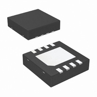
IC INVERTER REG SW CAP ADJ 8-LLP
Manufacturer
National Semiconductor
Type
Switched Capacitor (Charge Pump), Invertingr
Datasheet
1.LM2687MMNOPB.pdf
(10 pages)
Specifications of LM2687LD
Internal Switch(s)
Yes
Synchronous Rectifier
No
Number Of Outputs
1
Voltage - Output
-1.5 ~ -5.2 V
Current - Output
10mA
Frequency - Switching
110kHz
Voltage - Input
2.7 ~ 5.5 V
Operating Temperature
-40°C ~ 85°C
Mounting Type
Surface Mount
Package / Case
8-LLP
Power - Output
600mW
Lead Free Status / RoHS Status
Contains lead / RoHS non-compliant
Other names
LM2687LD
LM2687LDTR
LM2687LDTR
Available stocks
Company
Part Number
Manufacturer
Quantity
Price

Company:
Part Number:
LM2687LDX/NOPB
Manufacturer:
NS
Quantity:
1 404


www.national.com
Device Description
The LM2687 is an inverting, regulated charge-pump power
converter. It features low noise, small physical size, and is
simple to use. It is an ideal solution for biasing GaAsFET
devices such as power amplifier modules found in portable
devices and cellular phones.
A switched capacitor charge-pump circuit is used to invert
the input voltage V
which is seen at V
dropout linear regulator at V
age can be regulated anywhere from −1.5V to −5.2V and is
determined by a pair of feedback resistors (see Setting the
Output Voltage). The PSRR of the linear regulator reduces
the output voltage ripple produced by the charge-pump in-
verter to 1mV
also attenuates noise from the incoming supply due to its
high PSRR.
Shutdown
The LM2687 features a logic-level shutdown feature. The
function is active-low and will reduce the supply current to
0.05µA (typical) when engaged. When shutdown is active
V
Application Information
SETTING THE OUTPUT VOLTAGE
The output voltage on the LM2687 is set by using a resistor
divider between the output, the feedback pin, and an arbi-
trary voltage V
any positive voltage up to V
GND and should not be connected to a different voltage
unless it is well regulated so the output will stay constant.
The feedback pin is held at a constant voltage V
equals −1.2V. The output voltage can be selected using the
equation:
The current into the feedback pin I
to 100nA. Therefore using a value of 500kΩ or smaller for R
should make this current of little concern when setting the
output voltage. For best accuracy, use resistors with 1% or
better tolerance.
CAPACITOR SELECTION
Selecting the right capacitors for your circuit is important.
The capacitors affect the output resistance of the charge-
pump, the output voltage ripple, and the overall dropout
voltage (V
the charge-pump inverter is:
OUT
and V
IN
NEG
-|V
P-P
ADJ
OUT
are switched to ground.
(typical) at the output V
|) of the circuit. The output resistance of
(Figure 3). V
NEG
IN
to its corresponding negative value
. This voltage is regulated by a low
IN
OUT
. V
ADJ
ADJ
(Figure 3). The output volt-
FB
can range from GND to
is usually chosen to be
is in the range of 10nA
OUT
. The regulator
FB
which
1
8
The switching frequency is fixed at 100kHz and R
combined resistance of the internal switches) is typically
10Ω. It is clear from this equation that low ESR capacitors
are desirable and that larger values of C
the output resistance. The output resistance of the entire
circuit (in dropout) is:
R
approximately 10Ω. When the circuit is in regulation, the
overall output resistance is equal to the linear regulator load
regulation (5mV/mA). The dropout voltage is therefore af-
fected by the capacitors used since it is simply defined as
I
A larger value of capacitor and lower ESR for C
the output voltage ripple of the charge-pump. This ripple will
then be subject to the PSRR of the linear regulator and
reduced at V
further reduce this ripple.
The Low Dropout Linear Regulator uses an N-channel FET
device which behaves similarly to an NPN device. Because
of this and the internal compensation there are no strict ESR
requirements for the output capacitor to maintain stability.
Using the minimum recommended values will ensure stabil-
ity under all conditions.
In summation, larger value capacitors with lower ESR will
give the lowest output noise and ripple. C
should be 1.0µF minimum with less than 0.3Ω ESR. Larger
values may be used for any or all capacitors. All capacitors
should be either ceramic, surface-mount chip tantalum, or
polymer electrolytic.
OUTPUT NOISE AND RIPPLE
Low output noise and output voltage ripple are two of the
attractive features of the LM2687. Because they are small,
the noise and ripple (1mV typ.) can be hard to measure
accurately. Ground loop error between the circuit and the
oscilloscope caused by the switching of the charge-pump
produces ground currents in the probe wires. This causes
sharp voltage spikes on the oscilloscope waveform. To re-
duce this error measure, the output directly at the output
capacitor (C
not use the ground lead on the probe. Take the tip cover off
of the probe and touch the grounding ring of the probe
directly to the ground terminal of C
most accurate reading of the actual output waveform.
OUT
regulator
*
R
OUT
(the output impedance of the linear regulator) is
.
3
OUT
) and use the shortest wires possible. Also, do
. A larger value and lower ESR for C
R
OUT
= R
NEG
+ R
regulator
3
. This should give the
1
will further reduce
1
, C
2
2
will lower
, and C
SW
3
(the
will
3
Related parts for LM2687LD
Image
Part Number
Description
Manufacturer
Datasheet
Request
R

Part Number:
Description:
Low Noise Regulated Switched Capacitor Voltage
Manufacturer:
National Semiconductor Corporation
Datasheet:

Part Number:
Description:
National Semiconductor [8-Bit D/A Converter]
Manufacturer:
National Semiconductor
Datasheet:
Part Number:
Description:
National Semiconductor [Media Coprocessor]
Manufacturer:
National Semiconductor
Datasheet:
Part Number:
Description:
Digitally Controlled Tone and Volume Circuit with Stereo Audio Power Amplifier, Microphone Preamp Stage and National 3D Sound
Manufacturer:
National Semiconductor
Datasheet:
Part Number:
Description:
Digitally Controlled Tone and Volume Circuit with Stereo Audio Power Amplifier, Microphone Preamp Stage and National 3D Sound
Manufacturer:
National Semiconductor
Datasheet:
Part Number:
Description:
AC97 Rev 2 Codec with Sample Rate Conversion and National 3D Sound
Manufacturer:
National Semiconductor
Part Number:
Description:
Manufacturer:
National Semiconductor
Datasheet:
Part Number:
Description:
Manufacturer:
National Semiconductor
Datasheet:
Part Number:
Description:
General Purpose, Low Voltage, Low Power, Rail-to-Rail Output Operational Amplifiers
Manufacturer:
National Semiconductor
Datasheet:
Part Number:
Description:
8-bit 20 MSPS flash A/D converter.
Manufacturer:
National Semiconductor
Datasheet:
Part Number:
Description:
Low Noise Quad Operational Amplifier
Manufacturer:
National Semiconductor
Datasheet:
Part Number:
Description:
Quad Differential Line Receivers
Manufacturer:
National Semiconductor
Datasheet:
Part Number:
Description:
Quad High Speed Trapezoidal? Bus Transceiver
Manufacturer:
National Semiconductor
Datasheet:
Part Number:
Description:
Dual Line Receiver
Manufacturer:
National Semiconductor
Datasheet: