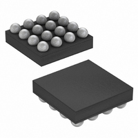
MAX8649EWE+T Maxim Integrated Products, MAX8649EWE+T Datasheet - Page 12

MAX8649EWE+T
Manufacturer Part Number
MAX8649EWE+T
Description
IC REG STEP-DOWN 1.8A 16-WLP
Manufacturer
Maxim Integrated Products
Type
Step-Down (Buck)r
Datasheet
1.MAX8649EWET.pdf
(32 pages)
Specifications of MAX8649EWE+T
Internal Switch(s)
Yes
Synchronous Rectifier
Yes
Number Of Outputs
1
Voltage - Output
0.75 ~ 1.38 V
Current - Output
1.8A
Frequency - Switching
3.25MHz
Voltage - Input
2.5 ~ 5.5 V
Operating Temperature
-40°C ~ 85°C
Mounting Type
Surface Mount
Package / Case
16-WLP
Power - Output
1.04W
Lead Free Status / RoHS Status
Lead free / RoHS Compliant
1.8A Step-Down Regulator with Differential
Remote Sense in 2mm x 2mm WLP
The MAX8649 DC-DC step-down regulator is
enabled/disabled using the EN logic input. The EN
input is able to handle input voltages up to V
ing that the EN logic input can be controlled by a wide
variety of signals/supplies.
The EN input has an internal pulldown resistor that
ensures EN is discharged during off conditions. This pull-
down resistor can be disabled through the CONTROL
register (see Table 7) once the MAX8649 is enabled,
achieving lowest possible quiescent current. When EN
is low, the CONTROL register is reset to default,
enabling the pulldown resistors on EN, VID0, and VID1.
See Figures 2 and 3 for detailed information on power-
up and power-down sequencing and operation mode
changes.
The MAX8649 operates in one of four modes deter-
mined by the state of the VID_ inputs (see Table 1). At
power-up, the MAX8649 is default set to operate in
power-save operation for MODE1 and forced-PWM
mode for MODE0, MODE2, and MODE3. For each of
the operation modes, MODE0 to MODE3, the MAX8649
DC-DC step-down regulator can be set to operate in
either power-save mode or forced-PWM mode. This is
Figure 2. Power-Up Sequence
12
A: POWER CONNECTED TO IN1 AND IN2.
B: EN LOGIC INPUT PULLED HIGH, OUTPUT VOLTAGE IS SET TO CONDITION DEFINED BY THE DEFAULT VALUE OF THE I
C: OUTPUT VOLTAGE IS SET TO CONDITION DEFINED BY THE I
D: OUTPUT VOLTAGE IS SET TO CONDITION DEFINED BY THE DEFAULT VALUE OF I
E: V
VID1
VID0
OUT
V
DD
EN
______________________________________________________________________________________
DD
IN
PULLED HIGH, ENABLING I
DC-DC Regulator Operating Modes
A
2
C INTERFACE.
2
C REGISTER FOR MODE1.
IN1
B
Enable
, ensur-
2
C REGISTER FOR MODE3.
1.27V
done by writing to the MODE_ registers (see Table 3 to
Table 6). The mode of operation can be changed at
any time.
In power-save mode, the MAX8649 PWM switching fre-
quency depends on the load current. For medium to
high load condition, the MAX8649 operates in fixed-
frequency PWM mode. For light load conditions, the
MAX8649 operates in hysteretic mode. The proprietary
hysteretic PWM control scheme ensures high efficien-
cy, fast switching, and fast transient response. This
control scheme is simple: when the output voltage is
below the regulation threshold, the error comparator
begins a switching cycle by turning on the high-side
switch. This switch remains on until the minimum on-
time expires and the output voltage is above the regu-
lation threshold plus hysteresis or the inductor current
is above the current-limit threshold. Once off, the high-
side switch remains off until the minimum off-time
expires and the output voltage falls again below the
regulation threshold. During the off period, the low-
side synchronous rectifier turns on and remains on
until either the high-side switch turns on again or the
inductor current approaches zero. The internal syn-
chronous rectifier eliminates the need for an external
Schottky diode.
C
1.23V
2
C REGISTER FOR MODE0 (SEE TABLE 1).
D
E
1.05V


