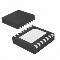
MAX8625AETD+T Maxim Integrated Products, MAX8625AETD+T Datasheet - Page 11

MAX8625AETD+T
Manufacturer Part Number
MAX8625AETD+T
Description
IC PWM STEP-UP/DWN REG 14-TDFN
Manufacturer
Maxim Integrated Products
Type
Step-Down (Buck), Step-Up (Boost)r
Datasheet
1.MAX8625AETDT.pdf
(16 pages)
Specifications of MAX8625AETD+T
Internal Switch(s)
Yes
Synchronous Rectifier
Yes
Number Of Outputs
1
Voltage - Output
3.3V, 1.25 ~ 4 V
Current - Output
800mA
Frequency - Switching
1MHz
Voltage - Input
2.5 ~ 5.5 V
Operating Temperature
-40°C ~ 85°C
Mounting Type
Surface Mount
Package / Case
14-TDFN Exposed Pad
Power - Output
1.48W
Lead Free Status / RoHS Status
Lead free / RoHS Compliant
or oscillation between the boost and buck modes as
seen in other step-up/down converters. See the switch-
ing waveforms for each of the three modes and transi-
tion waveforms in the Typical Operating Characteristics
section.
Drive SKIP high to operate the MAX8625A in forced-
PWM mode. In this mode, the IC operates at a constant
1MHz switching frequency with no pulse skipping. This
scheme is desirable in noise-sensitive applications
because the output ripple is minimized and has a pre-
dictable noise spectrum. Forced PWM consumes higher
supply current at light loads due to constant switching.
Drive SKIP low to operate the MAX8625A in skip mode
to improve light-load efficiency. In skip mode, the IC
switches only as necessary to maintain the output at
light loads, but still operates with fixed-frequency PWM
at medium and heavy loads. This maximizes light-load
efficiency and reduces the input quiescent current to
37µA (typ).
Do not dynamically transition between skip and FPWM.
The MAX8625A is not designed for dynamic transitions
between FPWM and skip modes. Spikes of negative
inductor current are possible when making these types
of dynamic transitions. The magnitude of the spike
depends on the load and output capacitance. The
MAX8625A has no protection against these types of
negative current spikes.
During a load transient, the output voltage instantly
changes due to the ESR of the output capacitors by an
amount equal to their ESR times the change in load
current (∆V
then deviates further based on the speed at which the
loop compensates for the load step. Increasing the out-
put capacitance reduces the output-voltage droop. See
the Capacitor Selection section. The typical application
circuit limits the output transient droop to less than 3%.
See the Typical Operating Characteristics section.
Load Regulation and Transient Response
OUT
= R
______________________________________________________________________________________
ESR
x ∆I
High-Efficiency, Seamless Transition,
LOAD
Forced-PWM Mode
). The output voltage
Step-Up/Down DC-DC Converter
Skip Mode
Soft-start prevents input inrush current during startup.
Internal soft-start circuitry ramps the peak inductor cur-
rent with an internal DAC in 8ms. Once the output
reaches regulation, the current limit immediately jumps
to the maximum threshold. This allows full load capabil-
ity as soon as regulation is reached, even if it occurs
before the 8ms soft-start time is complete.
When using the MAX8625A at low input voltages (close
to UVLO and < 3V), it is recommended that the ON pin
should not be tied to the BATT or supply voltage node
directly. The ON pin should be held low for > 1ms after
power to the MAX8625A is applied before it is driven
high for normal operation.
Drive ON low to place the MAX8625A in shutdown
mode and reduce supply current to less than 1µA.
During shutdown, OUT is disconnected from IN, and
LX1 and LX2 are connected to GND. Drive ON high for
normal operation.
The MAX8625A contains current-limit and thermal shut-
down circuitry to protect the IC from fault conditions.
When the inductor current exceeds the current limit (2A
for the MAX8625A), the converter immediately enters
phase 3 and an internal 100ms timer starts. The con-
verter continues to commutate through the three phas-
es, spending most of its time in phase 1 and phase 3. If
the overcurrent event continues and the output is out of
regulation for the duration of the 100ms timer, the IC
enters shutdown mode and the output latches off. ON
must then be toggled to clear the fault. If the overload
is removed before the 100ms timer expires, the timer is
cleared and the converter resumes normal operation.
The thermal-shutdown circuitry disables the IC switching
if the die temperature exceeds +165°C. The IC begins
soft-start once the die temperature cools by 15°C.
Fault and Thermal Shutdown
Shutdown
Soft-Start
11


