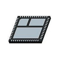
FDMF8705 Fairchild Semiconductor, FDMF8705 Datasheet - Page 10

FDMF8705
Manufacturer Part Number
FDMF8705
Description
IC MODULE DRIVER/FET POWER88-56
Manufacturer
Fairchild Semiconductor
Type
Step-Down (Buck)r
Datasheet
1.FDMF8705.pdf
(13 pages)
Specifications of FDMF8705
Internal Switch(s)
Yes
Synchronous Rectifier
Yes
Number Of Outputs
1
Current - Output
18A
Frequency - Switching
500kHz
Voltage - Input
12V
Operating Temperature
-55°C ~ 150°C
Mounting Type
Surface Mount
Package / Case
56-MLP
Power - Output
6.25W
Supply Voltage (min)
6.4 V
Supply Current
8 mA
Maximum Operating Temperature
+ 150 C
Mounting Style
SMD/SMT
Minimum Operating Temperature
- 55 C
Lead Free Status / RoHS Status
Lead free / RoHS Compliant
Voltage - Output
-
Lead Free Status / Rohs Status
Lead free / RoHS Compliant
Other names
FDMF8705TR
FDMF8705 Rev. C
Typical Application
Application Information
Supply Capacitor Selection
For the supply input (VCIN) of the FDMF8705, a local ceramic
bypass capacitor is recommended to reduce the noise and to
supply the peak current. Use at least a 1µF, X7R or X5R capac-
itor. Keep this capacitor close to the FDMF8705 VCIN and
CGND pins.
Bootstrap Circuit
The bootstrap circuit uses a charge storage capacitor (C
and the internal diode, as shown in Figure 26. Selection of
these components should be done after the high-side MOSFET
has been chosen. The required capacitance is determined
using the following equation:
where Q
and ∆V
MOSFET drive. For example, the Q
MOSFET is about 21nC @ 12V
~300mV, the required bootstrap capacitance is > 100nF. A good
quality ceramic capacitor must be used.
C
BOOT
BOOT
G
PWM
Controller
Signal
is the total gate charge of the high-side MOSFET,
GND
VCIN 12V
>=
VIN 12V
EN
is the voltage droop allowed on the high-side
LDRV
∆V
Power
GND
VCC
BOOT
Q
PWM1
PWM2
PWM3
PWM4
G
GS
. For an allowed droop of
G
of the internal high-side
Figure 26. Typical Application
PWM
VIN
CGND
PWM
VIN
CGND
PWM
VIN
CGND
PWM
VIN
CGND
(1)
HDRV
HDRV
HDRV
HDRV
BOOT
VCIN
VCIN
VCIN
VCIN
FDMF8705
FDMF8705
FDMF8705
FDMF8705
)
10
LDRV
LDRV
LDRV
LDRV
DISB
DISB
DISB
DISB
The average diode forward current, I
by:
where f
surge current rating of the internal diode should be checked
in-circuit, since this is dependent on the equivalent impedance
of the entire bootstrap circuit, including the PCB traces. For
applications requiring higher I
in parallel to the internal diode.
VSWH
VSWH
VSWH
VSWH
PGND
PGND
PGND
PGND
I
BOOT
BOOT
BOOT
BOOT
F(AVG)
SW
is the switching frequency of the controller. The peak
= Q
G
x f
SW
F
, an external diode may be used
F(AVG)
, can be estimated
VOUT
www.fairchildsemi.com
(2)


