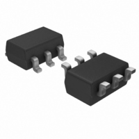
IRU3065CLTR International Rectifier, IRU3065CLTR Datasheet - Page 10

IRU3065CLTR
Manufacturer Part Number
IRU3065CLTR
Description
IC POS-NEG DC-DC CNTRLR SOT23-6
Manufacturer
International Rectifier
Type
Invertingr
Specifications of IRU3065CLTR
Internal Switch(s)
No
Synchronous Rectifier
No
Number Of Outputs
1
Voltage - Output
Adjustable
Current - Output
1A
Frequency - Switching
Adj to 1.5MHz
Voltage - Input
5V
Operating Temperature
0°C ~ 70°C
Mounting Type
Surface Mount
Package / Case
SOT-23-6
Power - Output
240mW
For Use With
IRDC3065 - LOW PWR SWTCH REG REF DESIGN KIT
Lead Free Status / RoHS Status
Contains lead / RoHS non-compliant
Available stocks
Company
Part Number
Manufacturer
Quantity
Price
Part Number:
IRU3065CLTRPBF
Manufacturer:
IR
Quantity:
20 000
IRU3065(PbF)
Operation-Regulation Mode
is operated in two modes depending on the load cur-
rent. When the load current is small, the buck boost
operated in first mode (regulation mode). The operation
waveforms are shown in figure 18. In this mode, the
inductor current in the buck converter is discontinuous.
Basic Operation
When the voltage at V
inside the IC is set and the V
trigger the PMOS in the power stage, the output induc-
tor current increases from zero. When sensed inductor
current voltage at I
10
THEORETICAL OPERATION
O u tp u t o f cu rre n t
co m p a ra to r
O u tp u t d i o d e
cu rre n t
In general, IRU3065 controlled buck boost converter
Figure 18 - Operation waveforms of IRU3065 con-
V
trolled buck boost converter at regulation mode.
V o l ta g e a cro ss
th e i n d u cto r
In d u cto r
cu rre n t
out
V
R
R
out
V i n
3
2
V g a te
I
peak
I
V
out
SEN
V
ref
D
SEN
pin reaches the internal current
pin is below zero, the flip-flop
t
on
GATE
T
s
pin output low, which
t
1
www.irf.com
reference of the chip, which is set to be 150mV (for
Vcc=5V), the flip-flop is reset and the PMOS is turned
off. The inductor current is discharged through diode
D2 to the load. The load voltage increases. When the
inductor current decreases to zero, the output current
is supplied by the output capacitor and the output volt-
age decreases until next cycle starts. In this mode, the
voltage at V
the output voltage is regulated at:
In the evaluation board, the output voltage is regulated
at -5V, as shown in figure 7. The steady state of the
converter should be operated in this mode. One feature
in this mode is that the shaded inductor current in fig-
ure 18 stays unchanged. The average output diode cur-
rent equals output current. When the switching period
decreases and frequency goes up, the average diode
current increases to support more output current. The
switching frequency increases linearly when the load
current increases as shown in figure 20.
1.083 10
4.583 10
f s I out
V out I out
Figure 20 - Theoretical switching frequency versus
versus output current for IRU3065 controlled buck
Figure 19 - Theoretical output voltage (-V
boost evaluation board.(assume VIsen=0.2V)
output current for evaluation board.(assume
0.75
6
4
-V
1.5 10
1.2 10
5
9 10
6 10
3 10
OUT
0.02
6
5
4
3
2
1
0
6
6
5
5
5
0.02
0
0
0
=
SEN
R3
R2
pin is controlled near zero. Therefore,
0.16
VIsen=0.2V)
V
0.2
REF
0.32
I out
I out
0.4
0.48
0.6
0.64
OUT
)
0.8
0.8
0.8
0.8


