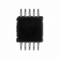
LM3354MM-1.8/NOPB National Semiconductor, LM3354MM-1.8/NOPB Datasheet - Page 4

LM3354MM-1.8/NOPB
Manufacturer Part Number
LM3354MM-1.8/NOPB
Description
IC CONV DC/DC BUCK/BOOST 10MSOP
Manufacturer
National Semiconductor
Type
Step-Down (Buck), Step-Up (Boost), Switched Capacitor (Charge Pump)r
Datasheet
1.LM3354MM-4.1NOPB.pdf
(12 pages)
Specifications of LM3354MM-1.8/NOPB
Internal Switch(s)
Yes
Synchronous Rectifier
No
Number Of Outputs
1
Voltage - Output
1.8V
Current - Output
90mA
Frequency - Switching
1MHz
Voltage - Input
2.5 ~ 5.5 V
Operating Temperature
-40°C ~ 85°C
Mounting Type
Surface Mount
Package / Case
10-MSOP, Micro10™, 10-uMAX, 10-uSOP
For Use With
LM3354-1.8EVAL - BOARD EVALUATION LM3354-1.8
Lead Free Status / RoHS Status
Lead free / RoHS Compliant
Power - Output
-
Other names
LM3354MM-1.8
LM3354MM-1.8TR
LM3354MM-1.8TR
www.national.com
LM3354-3.3
Output Voltage (V
OUT
Efficiency
Output Voltage
Ripple
(Peak-to-Peak)
LM3354-1.8
Output Voltage (V
OUT
Efficiency
Output Voltage
Ripple
(Peak-to-Peak)
LM3354-ALL OUTPUT VOLTAGE VERSIONS
Operating Quiescent
Current
Shutdown Quiescent
Current
Switching
Frequency
SD Input Threshold
Low
SD Input Threshold
High
SD Input Current
Electrical Characteristics
Limits in standard typeface are for T
less otherwise specified: C
Note 1: “Absolute Maximum Ratings” indicate limits beyond which damage to the device may occur. Operating Ratings are conditions for which the device is
intended to be functional, but device parameter specifications may not be guaranteed. For guaranteed specifications and test conditions, see “Electrical
Characteristics”.
Note 2: As long as T
The 5V option requires that T
Note 3: The human body model is a 100 pF capacitor discharged through a 1.5 kΩ resistor into each pin. The machine model is a 200 pF capacitor discharged
directly into each pin.
Note 4: Typical numbers are at 25˚C and represent the most likely norm.
Note 5: All limits guaranteed at room temperature (standard typeface) and at temperature extremes (bold typeface). All room temperature limits are 100% tested
or guaranteed through statistical analysis. All limits at temperature extremes are guaranteed by correlation using standard Statistical Quality Control methods (SQC).
All limits are used to calculate Average Outgoing Quality Level (AOQL).
Note 6: The V
Note 7: The output capacitor C
)
)
Parameter
OUT
pin is forced to 200 mV above the typical V
A
≤ +85˚C, all electrical characteristics hold true and the junction temperature should remain below +120˚C except for the 5V output option.
2.9V
1 mA
mA
2.5V
1 mA
mA
I
I
I
C
ceramic
2.9V
1 mA
mA
2.5V
1 mA
mA
I
I
I
C
ceramic
Measured at Pin
V
I
SD Pin at 0V (Note
7)
2.5V
2.5V
Measured at SD
Pin;
SD Pin = V
LOAD
LOAD
LOAD
LOAD
LOAD
LOAD
LOAD
IN
OUT
OUT
;
A
Conditions
≤ +60˚C.
OUT
<
<
= 70 mA
<
<
= 70 mA
<
<
= 15 mA
= 50 mA
= 15 mA
= 50 mA
<
<
<
<
= 10 µF
= 10 µF
= 0A (Note 6)
1
V
V
V
V
V
V
I
I
I
I
= C
is fully discharged before measurement.
LOAD
LOAD
LOAD
LOAD
IN
IN
IN
IN
IN
IN
IN
<
<
<
<
<
<
2
= 5.5V
= 0.33 µF; C
5.5V;
5.5V;
5.5V;
5.5V;
5.5V
5.5V
<
<
<
<
A
70
70
90
80
= 25˚C, and limits in boldface type apply over the full operating temperature range. Un-
(Continued)
3.201/3.168
3.201/3.168
1.728/1.710
1.728/1.710
IN
(Note 5)
0.8 V
= 10 µF; C
OUT
Min
0.6
. This is to insure that the internal switches are off.
IN
OUT
4
= 10 µF; C
(Note 4)
Typ
375
3.3
3.3
1.8
1.8
2.3
0.3
90
70
75
75
70
25
1
FIL
= 1 µF; V
IN
3.399/3.432
3.399/3.432
= 3.5V.
1.872/1.89
1.872/1.89
(Note 5)
0.2 V
Max
475
1.4
5
IN
mV
mV
Units
MHz
µA
µA
µA
%
%
V
V
V
V
P-P
P-P


