DS2411P+ Maxim Integrated Products, DS2411P+ Datasheet - Page 10
DS2411P+
Manufacturer Part Number
DS2411P+
Description
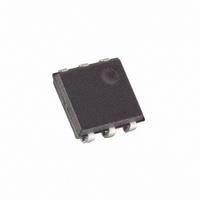
IC SILICON SERIAL NUMBER 6-TSOC
Manufacturer
Maxim Integrated Products
Datasheet
1.DS2411RTR.pdf
(11 pages)
Specifications of DS2411P+
Applications
*
Mounting Type
Surface Mount
Package / Case
6-TSOC
Data Bus Width
64 bit
Interface Type
1-Wire
Maximum Operating Temperature
+ 85 C
Minimum Operating Temperature
- 40 C
Mounting Style
SMD/SMT
Supply Voltage (max)
5.25 V
Supply Voltage (min)
1.5 V
Supply Voltage Range
1.5V To 5.25V
Operating Temperature Range
-40°C To +85°C
Digital Ic Case Style
TSOC
No. Of Pins
6
Peak Reflow Compatible (260 C)
Yes
Leaded Process Compatible
Yes
Rohs Compliant
Yes
Lead Free Status / RoHS Status
Lead free / RoHS Compliant


Slave to Master
A read-data time slot begins like a write-one time slot. The voltage on the data line must remain below
V
DS2411 will start pulling the data line low; its internal timing generator determines when this pull-down
ends and the voltage starts rising again. When responding with a 1, the DS2411 will not hold the data line
low at all, and the voltage starts rising as soon as t
The sum of t
side define the master sampling window (t
from the data line. For most reliable communication, t
should read close to but no later than t
t
time slot.
Improved Network Behavior
In a 1-Wire environment, line termination is possible only during transients controlled by the bus master
(1-Wire driver). 1-Wire networks therefore are susceptible to noise of various origins. Depending on the
physical size and topology of the network, reflections from end points and branch points can add up or
cancel each other to some extent. Such reflections are visible as glitches or ringing on the 1-Wire
communication line. A glitch during the rising edge of a time slot can cause a slave device to lose
synchronization with the master and, as a consequence, result in a search ROM command coming to a
dead end. For better performance in network applications, the DS2411 uses a new 1-Wire front end,
which makes it less sensitive to noise and also reduces the magnitude of noise injected by the slave
device itself.
The 1-Wire front end of the DS2411 differs from traditional slave devices in four characteristics.
1) The falling edge of the presence pulse has a controlled slew rate. This provides a better match to the
2) There is additional low-pass filtering in the circuit that detects the falling edge at the beginning of a
3) There is a hysteresis at the low-to-high switching threshold V
4) There is a time window specified by the rising edge hold-off time t
Only devices which have the parameters t
the improved 1-Wire front end.
SLOT
TLMIN
line impedance than a digitally switched transistor, converting the high frequency ringing known from
traditional devices into a smoother low-bandwidth transition. The slew rate control is specified by the
parameter t
time slot. This reduces the sensitivity to high-frequency noise. As a consequence, the duration of the
setup time t
not apply at Overdrive speed.
doesn’t go below V
at any 1-Wire speed.
ignored, even if they extend below V
droops or glitches that appear late after crossing the V
window cannot be filtered out and will be taken as beginning of a new time slot (Figure 8, Case C, t
t
is expired. This guarantees sufficient recovery time t
REH
until the read low time t
). The duration of the hold-off time is independent of the 1-Wire speed.
RL
FPD
SU
+ (rise rime) on one side and the internal timing generator of the DS2411 on the other
, which has different values for standard and Overdrive speed.
at standard speed is larger than with traditional devices. This additional filtering does
TH
- V
HY
, it will not be recognized (Figure 8, Case A). The hysteresis is effective
RL
is expired. During the t
MSRMAX
TH
FPD
MSRMIN
- V
, V
. After reading from the data line, the master must wait until
HY
HY
10 of 11
RL
threshold (Figure 8, Case B, t
to t
and t
is over.
RL
MSRMAX
REH
should be as short as permissible and the master
REC
specified in their electrical characteristics use
RL
) in which the master must perform a read
TH
for the DS2411 to get ready for the next
window, when responding with a 0, the
threshold and extend beyond the t
TH
. If a negative glitch crosses V
REH
during which glitches will be
GL
< t
REH
). Deep voltage
TH
REH
but
GL
Related parts for DS2411P+
Image
Part Number
Description
Manufacturer
Datasheet
Request
R

Part Number:
Description:
MAX7528KCWPMaxim Integrated Products [CMOS Dual 8-Bit Buffered Multiplying DACs]
Manufacturer:
Maxim Integrated Products
Datasheet:
Part Number:
Description:
Single +5V, fully integrated, 1.25Gbps laser diode driver.
Manufacturer:
Maxim Integrated Products
Datasheet:
Part Number:
Description:
Single +5V, fully integrated, 155Mbps laser diode driver.
Manufacturer:
Maxim Integrated Products
Datasheet:
Part Number:
Description:
VRD11/VRD10, K8 Rev F 2/3/4-Phase PWM Controllers with Integrated Dual MOSFET Drivers
Manufacturer:
Maxim Integrated Products
Datasheet:
Part Number:
Description:
Highly Integrated Level 2 SMBus Battery Chargers
Manufacturer:
Maxim Integrated Products
Datasheet:
Part Number:
Description:
Current Monitor and Accumulator with Integrated Sense Resistor; ; Temperature Range: -40°C to +85°C
Manufacturer:
Maxim Integrated Products
Part Number:
Description:
TSSOP 14/A�/RS-485 Transceivers with Integrated 100O/120O Termination Resis
Manufacturer:
Maxim Integrated Products
Part Number:
Description:
TSSOP 14/A�/RS-485 Transceivers with Integrated 100O/120O Termination Resis
Manufacturer:
Maxim Integrated Products
Part Number:
Description:
QFN 16/A�/AC-DC and DC-DC Peak-Current-Mode Converters with Integrated Step
Manufacturer:
Maxim Integrated Products
Part Number:
Description:
TDFN/A/65V, 1A, 600KHZ, SYNCHRONOUS STEP-DOWN REGULATOR WITH INTEGRATED SWI
Manufacturer:
Maxim Integrated Products
Part Number:
Description:
Integrated Temperature Controller f
Manufacturer:
Maxim Integrated Products
Part Number:
Description:
SOT23-6/I�/45MHz to 650MHz, Integrated IF VCOs with Differential Output
Manufacturer:
Maxim Integrated Products
Part Number:
Description:
SOT23-6/I�/45MHz to 650MHz, Integrated IF VCOs with Differential Output
Manufacturer:
Maxim Integrated Products
Part Number:
Description:
EVALUATION KIT/2.4GHZ TO 2.5GHZ 802.11G/B RF TRANSCEIVER WITH INTEGRATED PA
Manufacturer:
Maxim Integrated Products
Part Number:
Description:
QFN/E/DUAL PCIE/SATA HIGH SPEED SWITCH WITH INTEGRATED BIAS RESISTOR
Manufacturer:
Maxim Integrated Products
Datasheet: