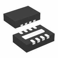
LTC4213CDDB#TRMPBF Linear Technology, LTC4213CDDB#TRMPBF Datasheet - Page 3

LTC4213CDDB#TRMPBF
Manufacturer Part Number
LTC4213CDDB#TRMPBF
Description
IC CIRC BREAK ELEC 8-DFN
Manufacturer
Linear Technology
Datasheet
1.LTC4213CDDBTRMPBF.pdf
(20 pages)
Specifications of LTC4213CDDB#TRMPBF
Applications
*
Mounting Type
Surface Mount
Package / Case
8-DFN
Linear Misc Type
Positive Low Voltage
Package Type
DFN EP
Operating Supply Voltage (min)
2.3V
Operating Supply Voltage (max)
6V
Operating Temperature (min)
0C
Operating Temperature (max)
70C
Operating Temperature Classification
Commercial
Product Length (mm)
3mm
Mounting
Surface Mount
Pin Count
8
Lead Free Status / RoHS Status
Lead free / RoHS Compliant
Available stocks
Company
Part Number
Manufacturer
Quantity
Price
SYMBOL
∆V
V
I
V
∆V
V
I
∆V
t
t
t
t
t
t
t
t
Note 1: Absolute Maximum Ratings are those values beyond which the life
of a device may be impaired.
ELECTRICAL CHARACTERISTICS
temperature range, otherwise specifications are at T
READY(LEAK)
ON(IN)
OV
FAULT(SLOW)
FAULT(FAST)
DEBOUNCE
READY
OFF
ON
RESET
READY(OL)
ON(TH)
ON(RST)
GSMAX
ON(HYST)
OV
– ∆V
GSARM
PARAMETER
Difference Between ∆V
∆V
READY Pin Output Low Voltage
READY Pin Leakage Current
ON Pin High Threshold
ON Pin Hysteresis
ON Pin Reset Threshold
ON Pin Input Current
Overvoltage Threshold
∆V
Overvoltage Protection Trip Time
V
V
Startup De-Bounce Time
READY Delay Time
Turn-Off Time
Turn-On Time
Reset Time
CB
CB(FAST)
GSARM
OV
Trips to GATE Discharging
= V
SENSEP
Trips to GATE Discharging
– V
CC
GSMAX
and
A
= 25°C. V
CONDITIONS
V
V
I
V
ON Rising, GATE Pulls Up
ON Falling, GATE Pulls Down
ON Falling, Fault Reset, GATE Pull Down
V
V
∆V
V
∆V
V
V
(Exiting Reset Mode)
V
V
V
V
(Normal Mode)
V
READY
SENSEN
SENSEN
READY
ON
SENSEP
SENSEN
SENSEP
ON
GATE
SENSEP
ON
ON
ON
SENSE
SENSE
The
= 1.2V
= 0V to 2V Step to Gate Rising,
= 2V to 0.6V Step to GATE Discharging
= 0.6V to 2V Step to GATE Rising,
Step 2V to 0V
= 0V to 8V Step to READY Rising,
= 1.6mA, Pull Down Device On
= 5V, Pull Down Device Off
●
Falling, V
= 5V
= V
= V
= 0, V
= 0, V
Step 0mV to 50mV,
Step 0V to 0.3V, V
CC
denotes the specifications which apply over the full operating
SENSEN
SENSEN
= 5V, I
CC
CC
Note 2: All currents into device pins are positive; all currents out of device
pins are negative. All voltages are referenced to ground unless otherwise
specified.
≥ 2.97V
= 2.3V
CC
= Step 5V to 6.2V
= 0
SEL
= V
SENSEP
= 0 unless otherwise noted. (Note 2)
SENSEN
= 5V
Falling,
●
●
●
●
●
●
●
●
●
●
0.15
0.76
0.36
0.41
MIN
0.3
1.5
10
25
27
22
20
7
4
TYP
1.1
0.8
0.2
0.8
0.4
0.7
40
65
16
60
50
80
0
0
1
5
8
LTC4213
MAX
0.84
0.44
160
130
115
150
0.4
1.1
2.5
±1
90
±1
27
10
16
UNITS
3
4213f
mV
µA
µA
µs
µs
µs
µs
µs
µs
µs
µs
V
V
V
V
V
V


