6N139#300 Avago Technologies US Inc., 6N139#300 Datasheet
6N139#300
Specifications of 6N139#300
Available stocks


Related parts for 6N139#300


6N139#300 Summary of contents
Page 1
Low Input Current, High Gain Optocouplers Technical Data Features • High Current Transfer Ratio – 2000% Typical (4500% Typical for HCNW139/138) • Low Input Current Requirements – 0.5 mA • TTL Compatible Output – 0 Typical OL • ...
Page 2
The 6N139, HCPL-0701, and CNW139 are for use in CMOS, LSTTL or other low power appli- cations. A 400% minimum current transfer ratio is guaranteed over operating range for only 0 LED current. The ...
Page 3
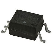
Ordering Information Specify Part Number followed by Option Number (if desired). Example: 6N139#XXXX 020 = 5000 V rms/1 Minute UL Rating Option* 300 = Gull Wing Surface Mount Option† 500 = Tape and Reel Packaging Option XXXE = Lead Free ...
Page 4
Package Outline Drawings 8-Pin DIP Package (6N139/6N138)** 9.65 ± 0.25 (0.380 ± 0.010 TYPE NUMBER A XXXXZ YYWW 1.19 (0.047) MAX. 3.56 ± 0.13 (0.140 ± 0.005) 1.080 ± 0.320 (0.043 ± ...
Page 5
Small Outline SO-8 Package (HCPL-0701/HCPL-0700 3.937 ± 0.127 (0.155 ± 0.005 PIN ONE 0.406 ± 0.076 (0.016 ± 0.003) * 5.080 ± 0.127 (0.200 ± 0.005) 3.175 ± 0.127 (0.125 ± 0.005) TOTAL PACKAGE LENGTH (INCLUSIVE ...
Page 6
Widebody DIP Package with Gull Wing Surface Mount Option 300 (HCNW139/HCNW138) 11.15 ± 0.15 (0.442 ± 0.006 1.78 ± 0.15 (0.070 ± 0.006) 2.54 (0.100) BSC DIMENSIONS IN MILLIMETERS (INCHES). LEAD COPLANARITY = ...
Page 7
Pb-Free IR Profile 260 +0/-5 ° 217 ° RAMP-UP 3 °C/SEC. MAX. 150 - 200 °C T smax T smin t s PREHEAT 60 to 180 SEC °C to PEAK TIME NOTES: THE ...
Page 8
IEC/EN/DIN EN 60747-5-2 Insulation Related Characteristics (HCNW139 and HCNW138) Description Installation Classification per DIN VDE 0110/1.89, Table 1 for rated mains voltage 600 V rms for rated mains voltage 1000 V rms Climatic Classification Pollution Degree (DIN VDE 0110/1.89) Maximum ...
Page 9
Absolute Maximum Ratings* Parameter Storage Temperature Operating Temperature** Average Forward Input Current Peak Forward Input Current (50% Duty Cycle Pulse Width) Peak Transient Input Current (<1 s Pulse Width, 300 pps) Reverse Input Voltage Input Power Dissipation Output ...
Page 10
Electrical Specifications 4 0 specified. All Typicals See Note 7. A Parameter Sym. Device Current Transfer CTR 6N139 Ratio HCPL-0701 HCNW139 6N139 HCPL-0701 ...
Page 11
Switching Specifications (AC) Over recommended operating conditions (T Parameter Sym. Device Propagation t 6N139 PHL Delay Time HCPL-0701 to Logic Low HCNW139 at Output 6N139 HCPL-0701 HCNW139 6N138 HCPL-0700 HCNW138 Propagation t 6N139 PLH Delay Time HCPL-0701 to Logic High ...
Page 12
Package Characteristics Parameter Sym. Input-Output Momentary V Withstand Voltage† Option 020 HCNW139 HCNW138 Resistance (Input-Output) R Capacitance (Input-Output) C **All typicals unless otherwise noted. A †The Input-Output Momentary Withstand Voltage is a dielectric voltage rating ...
Page 13
25° 1.0 2.0 V – OUTPUT VOLTAGE – Figure 1. 6N138/6N139 DC Transfer Characteristics. 1000 I F ...
Page 14
0 0.3 0.2 0 – FORWARD CURRENT F Figure 10. Logic Low Supply Current vs. ...
Page 15
V 90% 90 10% 10 SWITCH SWITCH AT ...
Page 16
For product information and a complete list of distributors, please go to our web site. For technical assistance call: Americas/Canada: +1 (800) 235-0312 or (916) 788-6763 Europe: +49 (0) 6441 92460 China: 10800 650 0017 Hong Kong: (+65) 6756 ...