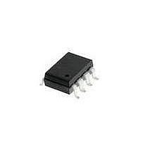
HCPL-7710-320E Avago Technologies US Inc., HCPL-7710-320E Datasheet - Page 13

HCPL-7710-320E
Manufacturer Part Number
HCPL-7710-320E
Description
OPTOCOUPLER 12MBD UL 8-SMD GW
Manufacturer
Avago Technologies US Inc.
Datasheet
1.HCPL-7710-000E.pdf
(18 pages)
Specifications of HCPL-7710-320E
Package / Case
8-SMD Gull Wing
Voltage - Isolation
5000Vrms
Number Of Channels
1, Unidirectional
Current - Output / Channel
10mA
Data Rate
12.5MBd
Propagation Delay High - Low @ If
20ns
Input Type
Logic
Output Type
Push-Pull, Totem-Pole
Mounting Type
Surface Mount, Gull Wing
Isolation Voltage
3750 Vrms
Maximum Continuous Output Current
10 mA
Maximum Fall Time
8 ns
Maximum Forward Diode Current
10 mA
Maximum Rise Time
9 ns
Output Device
Logic Gate Photo IC
Configuration
1 Channel
Maximum Baud Rate
12.5 MBps
Maximum Power Dissipation
150 mW
Maximum Operating Temperature
+ 100 C
Minimum Operating Temperature
- 40 C
Lead Free Status / RoHS Status
Lead free / RoHS Compliant
Available stocks
Company
Part Number
Manufacturer
Quantity
Price
Company:
Part Number:
HCPL-7710-320E
Manufacturer:
AVAGO
Quantity:
10 000
Part Number:
HCPL-7710-320E
Manufacturer:
AVAGO/安华高
Quantity:
20 000
13
Figure 18. Typical DeviceNet node.
Implementing DeviceNet and SDS with the HCPL-x710
With transmission rates up to 1 Mbit/s, both DeviceNet
and SDS are based upon the same broadcast-oriented,
communications protocol — the Controller Area
Network (CAN). Three types of isolated nodes are rec-
ommended for use on these networks: Isolated Node
Powered by the Network (Figure 19), Isolated Node
with Transceiver Powered by the Network (Figure 20),
and Isolated Node Providing Power to the Network
(Figure 21).
Figure 19. Isolated node powered by the network.
DRAIN/SHIELD
DRAIN/SHIELD
SIGNAL
POWER
SIGNAL
POWER
NETWORK
NETWORK
SUPPLY
POWER
SUPPLY
POWER
NODE/APP SPECIFIC
NODE/APP SPECIFIC
HCPL
HCPL
x710
x710
TRANSCEIVER
TRANSCEIVER
uP/CAN
uP/CAN
HCPL-0710 fig 17
HCPL
HCPL
x710
x710
HCPL-0710 fig 18
5 V REG.
SUPPLY
LOCAL
NODE
REG.
AC LINE
SWITCHING
ISOLATED
Isolated Node Powered by the Network
This type of node is very flexible and as can be seen in
Figure 19, is regarded as “isolated” because not all of its
components have the same ground reference. Yet, all
components are still powered by the network. This node
contains two regulators: one is isolated and powers the
CAN controller, node-specific application and isolated
(node) side of the two optocouplers while the other is
non-isolated. The non-isolated regulator supplies the
transceiver and the non-isolated (network) half of the
two optocouplers.
V+ (SIGNAL)
V– (SIGNAL)
V+ (POWER)
V– (POWER)
SUPPLY
POWER
GALVANIC
ISOLATION
BOUNDARY
V+ (SIGNAL)
V– (SIGNAL)
V+ (POWER)
V– (POWER)
GALVANIC
ISOLATION
BOUNDARY


