5962-9685201HYA Avago Technologies US Inc., 5962-9685201HYA Datasheet
5962-9685201HYA
Specifications of 5962-9685201HYA


Related parts for 5962-9685201HYA


5962-9685201HYA Summary of contents
Page 1
... MIL-PRF-38534 Class Level testing or from the DSCC Drawing 5962-96852. All devices are manufactured and tested on a MIL-PRF-38534 certified line and are included in the DSCC Qualified Manufacturers List QML-38534 for Hybrid Microcircuits ...
Page 2
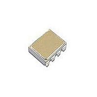
... NOTE: DIMENSIONS IN MILLIMETERS (INCHES). 2 HCPL-5300 HCPL-5301 HCPL-530K Gold Plate Option #200 Option #100 Option #300 5962- 9685201HPX 9685201HPC 9685201HPA 9685201HYC 9685201HYA 9685201HXA 5962- 9685201KPX 9685201KPC 9685201KPA 9685201KYC 9685201KYA 9685201KXA 8.13 (0.320) MAX. 7.16 (0.282) 7.57 (0.298) 4.32 (0.170) MAX. 3.81 (0.150) 0.20 (0.008) MIN. ...
Page 3
Device Marking Avago DESIGNATOR A QYYWWZ XXXXXX Avago P/N XXXXXXX DSCC SMD* DSCC SMD* XXX XXX PIN ONE/ 50434 ESD IDENT * QUALIFIED PARTS ONLY ;; ;; ; ; ; Hermetic Optocoupler Options Option Description 100 Surface mountable hermetic optocoupler ...
Page 4
Absolute Maximum Ratings Parameter Storage Temperature Operating Temperature Junction Temperature Lead Solder Temperature Average Input Current Peak Input Current (50% duty cycle pulse width) Peak Transient Input Current ( 1 s pulse width, 300 pps) Reverse Input Voltage ...
Page 5
Electrical Specifications Over recommended operating conditions ( 0.8 V) unless otherwise specified. F(OFF) Group A Parameter Symbol Subgroups Current Transfer CTR Ratio Low Level Output Current Low ...
Page 6
Switching Specifications ( External) L Over recommended operating conditions 0.8 V) unless otherwise specified. F(OFF) Group A Parameter Symbol Subgrps. Propagation t 9, 10, 11 PHL Delay Time to Low Output ...
Page 7
Switching Specifications (R = Internal Pull-up) L Over recommended operating conditions 0.8 V) unless otherwise specified. F(OFF) Group A Parameter Symbol Subgrps. Propagation t 9, 10, 11 PHL Delay Time to Low Output Level ...
Page 8
LED Drive Circuit Considerations For Ultra High CMR Performance Without a detector shield, the dominant cause of optocoupler CMR failure is capacitive coupling from the input side of the optocoupler, through the package, to the detector IC as shown in ...
Page 9
V will remain off and no common mode failure will occur. Even if the LED momentarily turns on, the 100 pF capacitor from pins 6-5 will keep the output from dipping below the ...
Page 10
125 °C 25 °C -55 ° – FORWARD LED CURRENT – Figure 1. Typical transfer characteristics 1000 T = 25°C A ...
Page 11
SHIELD V FF – 1000 V CM Figure 6. CMR test circuit. Typical CMR waveform 600 ...
Page 12
100 pF PLH PHL T = 25°C 400 A 300 200 100 – FORWARD LED CURRENT – Figure ...
Page 13
I I TOTAL* k CLEDP C 2 LED02 LEDP F 300 C LED01 I CLED01 LEDN 4 5 SHIELD * THE ARROWS INDICATE THE DIRECTION OF CURRENT FLOW FOR +dV /dt ...
Page 14
HCPL-5300 LED1 310 3 6 CMOS 4 5 SHIELD HCPL-5300 LED2 310 3 6 CMOS 4 5 SHIELD Figure 22. Typical application ...
Page 15
... MIL-PRF-38534 Class H, Class K, and DSCC SMD Test Program Avago Technologies’ Hi-Rel Optocouplers are in Q1 OFF compliance with MIL-PRF-38534 Classes H and K. Class H and Class K devices are also in compliance with DSCC Q2 ON drawing 5962-96852. Testing consists of 100% screening and quality conformance inspection to MIL-PRF-38534. (DUE TO OPTOCOUPLER PHL MAX ...
Page 16
For product information and a complete list of distributors, please go to our website: Avago, Avago Technologies, and the A logo are trademarks of Avago Technologies Limited in the United States and other countries. Data subject to change. Copyright © ...