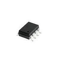
HCPL-3100-500E Avago Technologies US Inc., HCPL-3100-500E Datasheet - Page 10

HCPL-3100-500E
Manufacturer Part Number
HCPL-3100-500E
Description
OPTOCOUPLER GATE DRIVER 8-SMD
Manufacturer
Avago Technologies US Inc.
Datasheet
1.HCPL-3100.pdf
(14 pages)
Specifications of HCPL-3100-500E
Package / Case
8-SMD Gull Wing
Voltage - Isolation
5000Vrms
Number Of Channels
1, Unidirectional
Current - Output / Channel
100mA
Propagation Delay High - Low @ If
2µs @ 10mA
Current - Dc Forward (if)
20mA
Input Type
DC
Output Type
Push-Pull, Totem-Pole
Mounting Type
Surface Mount, Gull Wing
Isolation Voltage
5000 Vrms
Maximum Continuous Output Current
100 mA
Maximum Fall Time
0.5 us
Maximum Forward Diode Current
25 mA
Maximum Rise Time
0.5 us
Output Device
Integrated Photo IC
Configuration
1 Channel
Maximum Forward Diode Voltage
1.4 V
Maximum Reverse Diode Voltage
6 V
Maximum Power Dissipation
550 mW
Maximum Operating Temperature
+ 70 C
Minimum Operating Temperature
- 40 C
Number Of Elements
1
Forward Voltage
1.4V
Forward Current
25mA
Output Current
100mA
Package Type
PDIP SMD
Operating Temp Range
-40C to 100C
Fall Time
500ns
Rise Time
500ns
Power Dissipation
550mW
Propagation Delay Time
2000ns
Pin Count
8
Mounting
Surface Mount
Reverse Breakdown Voltage
6V
Operating Temperature Classification
Industrial
Lead Free Status / RoHS Status
Lead free / RoHS Compliant
Lead Free Status / RoHS Status
Lead free / RoHS Compliant, Lead free / RoHS Compliant
Figure 17. Normalized low to high threshold
input current vs. supply voltage, HCPL-3100.
10
Figure 14. Maximum power dissipation
vs. ambient temperature, HCPL-3101.
Figure 20. Normalized low to high threshold
input current vs. ambient temperature,
HCPL-3101.
600
500
400
300
200
100
120
110
100
120
110
100
90
80
70
90
80
70
60
0
-40 -25
-40
15
-20
AMBIENT TEMPERATURE T
AMBIENT TEMPERATURE T
18
SUPPLY VOLTAGE V
I
0
FLH
VALUE OF V
0
= 100% at T
ASSUME 100
25
21
20
P
O
50
CC
40
P
24
A
= 24 V
tot
= 25 C
CC
75 85 100
T
60
A
(V)
A
V
A
= 25 C
CC
( C)
27
( C)
= 24 V
80
125
100
30
Figure 15. Typical forward current vs. forward
voltage, HCPL-3100.
Figure 18. Normalized low to high threshold
input current vs. supply voltage, HCPL-3101.
Figure 21. Typical low level output 1 voltage
vs. output 1 current, HCPL-3100.
100
120
110
100
0.1
10
90
80
70
1
0.50
3
2
1
0
15
0
T
A
50 C
= 100 C
85 C
0.75
0.1
18
O
FORWARD VOLTAGE V
1
I
SUPPLY VOLTAGE V
FLH
OUTPUT CURRENT I
1.00
0.2
= 100% at V
21
1.25
0.3
CC
24
T
V
V
I
25 C
0 C
-40 C
1.50
F
A
CC1
CC2
0.4
= 24 V
CC
= 10 mA
T
= 25 C
F
O1
A
(V)
(V)
= 12 V
= -12 V
= 25 C
(A)
27
1.75
0.5
2.00
0.6
30
Figure 19. Normalized low to high threshold
input current vs. ambient temperature,
HCPL-3100.
Figure 16. Typical forward current vs. forward
voltage, HCPL-3101.
Figure 22. Typical low level output 1 voltage
vs. output 1 current, HCPL-3101.
160
140
120
100
100
0.1
80
60
10
1
3
2
1
0
-40
1.0
0
I
FLH
T
50 C
25 C
V
A
-20
CC
AMBIENT TEMPERATURE T
= 85 C
= 100% at T
0.1
1.2
O
= 24 V
FORWARD VOLTAGE V
1
OUTPUT CURRENT I
0
1.4
0.2
A
20
= 25 C
1.6
0.3
40
T
V
V
I
F
1.8
A
0.4
CC1
CC2
= 5 mA
-20 C
-40 C
60
= 25 C
F
O1
0 C
(V)
A
= 12 V
= -12 V
(A)
( C)
2.0
0.5
80
100
2.2
0.6


