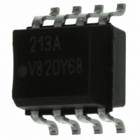
IL213AT Vishay, IL213AT Datasheet - Page 4

IL213AT
Manufacturer Part Number
IL213AT
Description
OPTOCOUPLER PHOTOTRNS 100% 8SOIC
Manufacturer
Vishay
Specifications of IL213AT
Mounting Type
Surface Mount
Isolation Voltage
4000 Vrms
Number Of Channels
1
Input Type
DC
Voltage - Isolation
4000Vrms
Current Transfer Ratio (min)
100% @ 10mA
Voltage - Output
30V
Current - Dc Forward (if)
60mA
Vce Saturation (max)
400mV
Output Type
Transistor with Base
Package / Case
8-SOIC (3.9mm Width)
Maximum Input Diode Current
60 mA
Maximum Reverse Diode Voltage
6 V
Output Device
Phototransistor
Configuration
1 Channel
Maximum Collector Emitter Voltage
30 V
Maximum Collector Emitter Saturation Voltage
0.4 V
Current Transfer Ratio
130 %
Maximum Forward Diode Voltage
1.5 V
Maximum Collector Current
100 mA
Maximum Power Dissipation
240 mW
Maximum Operating Temperature
+ 100 C
Minimum Operating Temperature
- 55 C
No. Of Channels
1
Optocoupler Output Type
Phototransistor
Input Current
10mA
Output Voltage
30V
Opto Case Style
SOIC
No. Of Pins
8
Approval Bodies
UL1577, DIN EN
Rohs Compliant
Yes
Lead Free Status / RoHS Status
Lead free / RoHS Compliant
Current - Output / Channel
-
Current Transfer Ratio (max)
-
Lead Free Status / Rohs Status
Lead free / RoHS Compliant
Other names
751-1287-2
IL213ATGITR
IL213ATGITR
IL213ATGITR
IL213ATGITR
Available stocks
Company
Part Number
Manufacturer
Quantity
Price
Company:
Part Number:
IL213AT
Manufacturer:
INFINEON
Quantity:
6 210
Company:
Part Number:
IL213AT
Manufacturer:
JRC
Quantity:
6 210
Part Number:
IL213AT
Manufacturer:
VISHAY/威世
Quantity:
20 000
IL211AT/ 212AT/ 213AT
Vishay Semiconductors
www.vishay.com
4
iil211at_05
iil211at_06
iil211at_07
Figure 5. Normalized Collector-Base Photocurrent vs. LED
1000
10 -1
.01
10 -2
10 4
10 3
10 2
10 0
100
10 5
10
Figure 6. Collector-Base Photocurrent vs. LED Current
10 1
.1
Figure 7. Collector-Emitter Leakage Current vs.Temp.
10
1
.1
1
.1
.1
-20
Normalized to:
V CB = 9.3 V
I F =10 mA
T A = 25°C
T A = 25°C
V CB = 9.3 V
0
T A - Ambient Temperature - °C
I F - LED Current - mA
1
1
I F - LED Current - mA
20
Current
40
Typical
V CE = 10 V
10
10
60
80
100
100
100
iil211at_08
Figure 9. Typical Switching Characteristics vs. Base Resistance
iil211at_09
iil211at_10
1000
Figure 8. Normalized Saturated HFE vs. Base Current and
100
500
100
Figure 10. Typical Switching Times vs. Load Resistance
1.0
50
10
50
10
2.0
1.5
1.0
0.5
0.0
5
5
1
0.1
10K
1
Vce = 0.4 V
25°C
Input:
I F =10 mA
Pulse width = 100 mS
Duty cycle = 50%
Input:
Pulse width = 100 mS
Duty cycle = 50%
I F =10 mA
Base-emitter resistance, R BE (Ω)
0.5
70°C
(Saturated Operation)
Load resistance RL (KΩ)
50K
Ib - Base Current - µA
50°C
1 0
1
Temperature
100K
5
Normalized to:
100
10
Ib = 20 µA
Vce = 10 V
Ta = 25°C
Document Number 83615
Rev. 1.5, 26-Oct-04
500K
50 100
1000
1M


