TCMT1109 Vishay, TCMT1109 Datasheet - Page 4
TCMT1109
Manufacturer Part Number
TCMT1109
Description
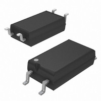
OPTOCPL PHOTOTRANS 1CH 400% 4SOP
Manufacturer
Vishay
Specifications of TCMT1109
Isolation Voltage
3750 Vrms
Number Of Channels
1
Input Type
DC
Voltage - Isolation
3750Vrms
Current Transfer Ratio (min)
200% @ 5mA
Current Transfer Ratio (max)
400% @ 5mA
Voltage - Output
70V
Current - Output / Channel
50mA
Current - Dc Forward (if)
60mA
Vce Saturation (max)
300mV
Output Type
Transistor
Mounting Type
Surface Mount
Package / Case
4-SOP
Forward Current
60 mA
Maximum Input Diode Current
60 mA
Maximum Reverse Diode Voltage
6 V
Output Device
Transistor
Configuration
1
Maximum Collector Emitter Voltage
70 V
Maximum Collector Emitter Saturation Voltage
300 mV
Current Transfer Ratio
400 %
Maximum Forward Diode Voltage
1.6 V
Maximum Collector Current
50 mA
Maximum Power Dissipation
250 mW
Maximum Operating Temperature
+ 100 C
Minimum Operating Temperature
- 40 C
No. Of Channels
1
Optocoupler Output Type
Phototransistor
Input Current
50mA
Output Voltage
70V
Opto Case Style
SOP
No. Of Pins
4
Propagation Delay
6µs
Lead Free Status / RoHS Status
Lead free / RoHS Compliant
Lead Free Status / RoHS Status
Lead free / RoHS Compliant, Lead free / RoHS Compliant
Available stocks
Company
Part Number
Manufacturer
Quantity
Price

Part Number:
TCMT1109
Manufacturer:
VISHAY/威世
Quantity:
20 000


TCMT1100 Series, TCMT4100 Series
Vishay Semiconductors
Note
• As per IEC 60747-5-5, § 7.4.3.8.1, this optocoupler is suitable for “safe electrical insulation” only within the safety ratings. Compliance with
TYPICAL CHARACTERISTICS (T
www.vishay.com
4
SAFETY AND INSULATION RATINGS
PARAMETER
Climatic classification
Comparative tracking index
V
V
P
I
T
Creepage distance
Clearance distance
Insulation thickness, reinforced rated
SI
the safety ratings shall be ensured by means of protective circuits.
IOTM
IORM
SI
SO
Fig. 4 - Total Power Dissipation vs. Ambient Temperature
96 11700
t
t
t
t
p
d
r
on
(= t
100 %
10 %
300
250
200
150
100
90 %
d
50
+ t
0
I
I
C
F
0
0
0
r
)
Phototransistor
IR-diode
T
Coupled device
amb
t
Pulse duration
Delay time
Rise time
Turn-on time
d
t
Fig. 3 - Switching Times
on
t
- Ambient Temperature (°C)
r
40
t
p
t
t
t
t
For technical questions, contact:
s
off
f
s
80
(= t
s
t
Optocoupler, Phototransistor Output,
off
+ t
t
f
f
amb
)
Single/Quad Channel, Half Pitch
= 25 °C, unless otherwise specified)
Storage time
Fall time
Turn-off time
120
per IEC60950 2.10.5.1
TEST CONDITION
96 11698
t
t
IEC 68 part 1
Mini-Flat Package
optocoupleranswers@vishay.com
96 11862
SYMBOL
CTI
1000
100
Fig. 5 - Forward Current vs. Forward Voltage
0.1
10
1
0
MIN.
6000
175
707
0.4
0.4
V
5
5
F
- Forward Voltage (V)
0.8
40/110/21
TYP.
1.2
Document Number: 83510
1.6
Rev. 2.3, 04-Nov-10
MAX.
399
265
130
150
2.0
UNIT
mW
mm
mm
mm
mA
°C
V
V
Related parts for TCMT1109
Image
Part Number
Description
Manufacturer
Datasheet
Request
R

Part Number:
Description:
Optocoupler With Phototransistor Output
Manufacturer:
Vishay
Datasheet:
Part Number:
Description:
357-036-542-201 CARDEDGE 36POS DL .156 BLK LOPRO
Manufacturer:
Vishay
Datasheet:
Part Number:
Description:
357-036-542-201 CARDEDGE 36POS DL .156 BLK LOPRO
Manufacturer:
Vishay
Datasheet:
Part Number:
Description:
357-036-542-201 CARDEDGE 36POS DL .156 BLK LOPRO
Manufacturer:
Vishay
Datasheet:
Part Number:
Description:
357-036-542-201 CARDEDGE 36POS DL .156 BLK LOPRO
Manufacturer:
Vishay
Datasheet:
Part Number:
Description:
357-036-542-201 CARDEDGE 36POS DL .156 BLK LOPRO
Manufacturer:
Vishay
Datasheet:
Part Number:
Description:
357-036-542-201 CARDEDGE 36POS DL .156 BLK LOPRO
Manufacturer:
Vishay
Datasheet:
Part Number:
Description:
357-036-542-201 CARDEDGE 36POS DL .156 BLK LOPRO
Manufacturer:
Vishay
Datasheet:
Part Number:
Description:
357-036-542-201 CARDEDGE 36POS DL .156 BLK LOPRO
Manufacturer:
Vishay
Datasheet:
Part Number:
Description:
357-036-542-201 CARDEDGE 36POS DL .156 BLK LOPRO
Manufacturer:
Vishay
Datasheet:
Part Number:
Description:
357-036-542-201 CARDEDGE 36POS DL .156 BLK LOPRO
Manufacturer:
Vishay
Datasheet:
Part Number:
Description:
357-036-542-201 CARDEDGE 36POS DL .156 BLK LOPRO
Manufacturer:
Vishay
Datasheet:
Part Number:
Description:
357-036-542-201 CARDEDGE 36POS DL .156 BLK LOPRO
Manufacturer:
Vishay
Datasheet:
Part Number:
Description:
357-036-542-201 CARDEDGE 36POS DL .156 BLK LOPRO
Manufacturer:
Vishay
Datasheet:
Part Number:
Description:
357-036-542-201 CARDEDGE 36POS DL .156 BLK LOPRO
Manufacturer:
Vishay
Datasheet: