IL212AT Vishay, IL212AT Datasheet

OPTOCOUPLER PHOTOTRANS 50% 8SOIC

IL212AT

Manufacturer Part Number
IL212AT
Description
OPTOCOUPLER PHOTOTRANS 50% 8SOIC
Manufacturer
Vishay
Datasheet

Specifications of IL212AT

Mounting Type
Surface Mount
Number Of Channels
1
Input Type
DC
Voltage - Isolation
4000Vrms
Current Transfer Ratio (min)
50% @ 10mA
Voltage - Output
30V
Current - Dc Forward (if)
60mA
Vce Saturation (max)
400mV
Output Type
Transistor with Base
Package / Case
8-SOIC (3.9mm Width)
No. Of Channels
1
Optocoupler Output Type
Phototransistor
Input Current
10mA
Output Voltage
30V
Opto Case Style
SOIC
No. Of Pins
8
Isolation Voltage
4kV
Configuration
1 Channel
Maximum Collector Emitter Voltage
30 V
Maximum Collector Emitter Saturation Voltage
0.4 V
Current Transfer Ratio
80 %
Maximum Forward Diode Voltage
1.5 V
Maximum Collector Current
100 mA
Maximum Power Dissipation
240 mW
Maximum Operating Temperature
+ 100 C
Minimum Operating Temperature
- 55 C
Maximum Input Diode Current
60 mA
Maximum Reverse Diode Voltage
6 V
Output Device
Phototransistor
Lead Free Status / RoHS Status
Lead free / RoHS Compliant
Current - Output / Channel
-
Current Transfer Ratio (max)
-
Lead Free Status / Rohs Status
 Details

Available stocks

Company
Part Number
Manufacturer
Quantity
Price
Part Number:
IL212AT
Manufacturer:
Vishay Semiconductors
Quantity:
1 995
Part Number:
IL212AT
Manufacturer:
SIEMENS
Quantity:
5 510
Part Number:
IL212AT
Manufacturer:
INFINEON/英飞凌
Quantity:
20 000
DESCRIPTION
The IL211AT, IL212AT, IL213AT are optically coupled pairs
with a gallium arsenide infrared LED and silicon NPN
phototransistor. Signal information, including a DC level,
can be transmitted by the device while maintaining a high
degree of electrical isolation between input and output.
The IL211AT, IL212AT, IL213AT comes in a standard
SOIC-8 small outline package for surface mounting which
makes it ideally suited for high density applications with
limited space. In addition to eliminating through-holes
requirements, this package conforms to standards for
surface mounted devices.
A choice of 20 %, 50 %, and 100 % minimum CTR at
I
of different applications.
Document Number: 83615
Rev. 1.9, 21-Dec-10
F
ORDERING INFORMATION
AGENCY CERTIFIED/PACKAGE
UL, cUL
SIOC-8
ABSOLUTE MAXIMUM RATINGS (T
PARAMETER
INPUT
Peak reverse voltage
Forward continuous current
Power dissipation
Derate linearly from 25 °C
OUTPUT
Collector emitter breakdown voltage
Emitter collector breakdown voltage
Collector base breakdown voltage
I
I
Power dissipation
Derate linearly from 25 °C
i179025
= 10 mA makes these optocouplers suitable for a variety
CMAX DC
CMAX
I
L
Optocoupler, Phototransistor Output,
NC
NC
A
K
i179002-1
with Base Connection in SOIC-8
For technical questions, contact:
1
2
3
4
2
PART NUMBER
amb
D E
1
V
8
7
6
5
= 25 °C, unless otherwise specified)
TEST CONDITION
NC
B
C
E
IL211AT
> 20
t < 1 ms
#
optocoupleranswers@vishay.com
FEATURES
• Isolation test voltage, 4000 V
• Industry standard SOIC-8 surface mountable
• Compatible with dual wave, vapor phase and IR
• Compliant to RoHS Directive 2002/95/EC and in
AGENCY APPROVALS
• UL1577, file no. E52744 system code Y
• cUL - file no. E52744, equivalent to CSA bulletin 5A
• DIN EN 60747-5-2 (VDE 0884)
• DIN EN 60747-5-5 (pending)
Note
(1)
package
reflow soldering
accordance to WEEE 2002/96/EC
Available upon request, as option 1
A
SYMBOL
I
CMAX DC
BV
BV
IL211AT, IL212AT, IL213AT
I
V
P
P
CMAX
V
CBO
I
diss
diss
CEO
ECO
F
R
CTR (%)
IL212AT
10 mA
> 50
T
Vishay Semiconductors
VALUE
100
150
1.2
60
90
30
70
50
6
7
2
RMS
(1)
(1)
IL213AT
6.1 mm
> 100
IOC-8
www.vishay.com
mW/°C
mW/°C
UNIT
mW
mW
mA
mA
mA
V
V
V
V
1

Related parts for IL212AT

IL212AT Summary of contents

Page 1

... NC 4 i179002-1 i179025 DESCRIPTION The IL211AT, IL212AT, IL213AT are optically coupled pairs with a gallium arsenide infrared LED and silicon NPN phototransistor. Signal information, including a DC level, can be transmitted by the device while maintaining a high degree of electrical isolation between input and output. The IL211AT, IL212AT, IL213AT comes in a standard ...

Page 2

... IL211AT, IL212AT, IL213AT Vishay Semiconductors ABSOLUTE MAXIMUM RATINGS (T PARAMETER COUPLER Isolation test voltage Total package dissipation Derate linearly from 25 °C Storage temperature Operating temperature Soldering time Note • Stresses in excess of the absolute maximum ratings can cause permanent damage to the device. Functional operation of the device is not implied at these or any other conditions in excess of those given in the operational sections of this document ...

Page 3

... °C amb 100 Fig Leakage Current vs. Ambient Temperature Fig Collector Current vs. Collector Emitter Voltage (sat) optocoupleranswers@vishay.com IL211AT, IL212AT, IL213AT Vishay Semiconductors MIN. TYP. MAX. 55/100/21 175 399 6000 560 350 150 165 4 4 0.2 10 000 I ...

Page 4

... IL211AT, IL212AT, IL213AT Vishay Semiconductors 1 1 0.8 0 Ambient Temperature (°C) 22490 amb Fig Normalized CTR (NS) vs. Ambient Temperature 1 1 0.8 0 0.4 0 Ambient Temperature (°C) 22489 amb Fig Normalized CTR (sat) vs. Ambient Temperature 1.2 1 °C amb °C amb 0 ° ...

Page 5

... Fig Switching Time vs. Load Resistance Document Number: 83615 For technical questions, contact: Rev. 1.9, 21-Dec- 1000 22492 Fig Switching Time vs. Base Emitter Resistance 100 C t off 100 optocoupleranswers@vishay.com IL211AT, IL212AT, IL213AT Vishay Semiconductors 100 Pul e width = 100 μ kHz 2.2 kΩ off 100 1000 10 000 Emitter Re i tance (kΩ ...

Page 6

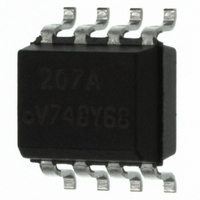
... IL211AT, IL212AT, IL213AT Vishay Semiconductors PACKAGE DIMENSIONS in millimeters 3.05 ± 0.13 6.10 Pin one ID 4.88 ± 0.13 ISO method A 0.1 0.2 i178003 PACKAGE MARKING (example) www.vishay.com For technical questions, contact: 6 Optocoupler, Phototransistor Output, with Base Connection in SOIC-8 Package C L 3.91 ± 0.13 0.41 0.38 ± ...

Page 7

... Vishay product could result in personal injury or death. Customers using or selling Vishay products not expressly indicated for use in such applications their own risk and agree to fully indemnify and hold Vishay and its distributors harmless from and against any and all claims, liabilities, expenses and damages arising or resulting in connection with such use or sale, including attorneys fees, even if such claim alleges that Vishay or its distributor was negligent regarding the design or manufacture of the part ...

Related keywords