TLP127(TPL) Toshiba, TLP127(TPL) Datasheet
TLP127(TPL)
Specifications of TLP127(TPL)


Related parts for TLP127(TPL)


TLP127(TPL) Summary of contents
Page 1
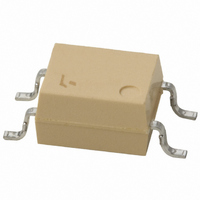
... TOSHIBA Photocoupler GaAs Ired & Photo−Transistor Programmable Controllers DC−Output Module Telecommunication The TOSHIBA mini flat coupler TLP127 is a small outline coupler, suitable for surface mount assembly. TLP127 consists of a gallium arsenide infrared emitting diode, optically coupled to a darlington photo transistor with an integral base−emitter resistor, and provides 300V V ...
Page 2
... Please design the appropriate reliability upon reviewing the Toshiba Semiconductor Reliability Handbook (“Handling Precautions”/“Derating Concept and Methods”) and individual reliability data (i.e. reliability test report and estimated failure rate, etc). ...
Page 3
Individual Electrical Characteristics Characteristic Forward voltage Reverse current Capacitance Collector−emitter breakdown voltage Emitter−collector breakdown voltage Collector dark current Capacitance collector to emitter Coupled Electrical Characteristics Characteristic Current transfer ratio Saturated CTR Collector−emitter saturation voltage Isolation Characteristics Characteristic Capacitance (input to ...
Page 4
Switching Characteristics Characteristic Rise time Fall time Turn−on time Turn−off time Turn−on time Storage time Turn−off time Recommended Operating Conditions Characteristic Supply voltage Forward current Collector current Operating temperature Note: Recommended operating conditions are given as a design guideline to ...
Page 5
I – 100 − Ambient temperature Ta (°C) I – 3000 Pulse width ≤ 100μ 25°C 1000 500 300 100 ...
Page 6
I – 160 Ta = 25°C 10mA 120 0.8 1.2 1.6 0.4 Collector–emitter voltage V CE Switching Time – 1000 Ta = 25°C V 500 300 16mA) ...
Page 7
I – Ta CEO − 200V 150V 80V − − − Ambient temperature Ta (℃) 120 100 ...
Page 8
... Product shall not be used for or incorporated into any products or systems whose manufacture, use, or sale is prohibited under any applicable laws or regulations. • The information contained herein is presented only as guidance for Product use. No responsibility is assumed by TOSHIBA for any infringement of patents or any other intellectual property rights of third parties that may result from the use of Product. No license to any intellectual property right is granted by this document, whether express or implied, by estoppel or otherwise. • ...