944U101K801AAM Cornell Dubilier Electronics (CDE), 944U101K801AAM Datasheet - Page 3
944U101K801AAM
Manufacturer Part Number
944U101K801AAM
Description
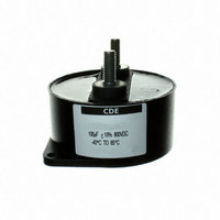
CAP 100UF 800V FILM POWER
Manufacturer
Cornell Dubilier Electronics (CDE)
Series
944Ur
Datasheet
1.944U330K142AAM.pdf
(3 pages)
Specifications of 944U101K801AAM
Capacitance
100µF
Tolerance
±10%
Lead Spacing
1.772" (45.00mm)
Voltage - Dc
800V
Dielectric Material
Polypropylene, Metallized
Esr (equivalent Series Resistance)
0.5 mOhm
Operating Temperature
-40°C ~ 85°C
Mounting Type
Chassis Mount
Package / Case
Radial, Can - Screw Terminals
Size / Dimension
3.327" Dia (84.50mm)
Height
1.575" (40.00mm)
Termination
Screw Terminals
Features
EMI Suppression
Voltage Rating
800 Volts
Esr
0.5 mOhms
Termination Style
Screw
Dimensions
84.5 mm Dia. x 40 mm L
Operating Temperature Range
- 40 C to + 85 C
Load Life
10000 Hrs
Product
DC Link Film Capacitors
Capacitor Application
DC Link
Capacitor Dielectric Type
Polypropylene
Capacitance Tolerance
± 10%
Capacitor Case Style
Can
Capacitor Mounting
Panel
Rohs Compliant
Yes
Capacitor Terminals
Screw
Lead Free Status / RoHS Status
Lead free / RoHS Compliant
Voltage - Ac
-
Lead Free Status / Rohs Status
Lead free / RoHS Compliant
Other names
338-1918


Type 944U Polypropylene Film Capacitor for DC Filtering
Metallized Polypropylene Dielectric
Expected Lifetime Predictions
To use the Expected Lifetime curves calculate Va ⁄Vr and core
temperature T. Start by estimating:
Units:
NOTE: The temperature rise in the 944U is I²(ESR) times the
thermal resistance θ. The ESR is mainly the metal resistance;
the metal resistance is the 10 kHz ESR. For operation below 10kHz
add the dielectric resistance. It is the dielectric dissipation factor—
no more than 0.0002—times the capacitive reactance, i.e., 0.0002
⁄(2πfC).
That’s equal to 31.83 ⁄(fC).
CDE Cornell Dubilier • 1605 E. Rodney French Blvd. • New Bedford, MA 02744 • Phone: (508)996-8561 • Fax: (508)996-3830
A=m²
C=μF
ESR=mΩ
f=kHz
I=A
Applied dc voltage Va
Ripple Current I
Ripple Frequency f
Ambient Temperature Ta
Airflow speed v
1.7
1.6
1.5
1.4
1.3
1.2
1.1
0.9
0.8
As an illustration at 50 °C the expected lifetime is 100,000 h with the 24-hour Va ∕ Vr.
Expected lifetime can be calculated for varying exposure to overvoltage transients.
Expected Lifetime vs Core Temperature and Applied DC Voltage
1
The expected lifetime predictions assume no exposure to overvoltage transients.
100
Va &Vr=Vdc
T, Ta & Tc=°C
v=m/s
θ, θca & θcc =°C/W
For applications with more severe 24-hour profiles, contact us.
COPY & PASTE A CDE PART NUMBER TO CHECK STOCK ONLINE:
1000
Va / Vr
Expected Lifetime (h)
1.67
1.50
1.30
1.10
1.00
1. Start with the 10 kHz ESR from the Ratings table. If frequency is less
than 10 kHz, add 31.83 ⁄(fC).
2. Compute total thermal resistance θ as the sum of core-to-case
thermal resistance θcc and case-to-ambient thermal resistance
θca. Both are in the Ratings table but θca is for still air and θcc
is for 10 kHz or less. For frequency > 10 kHz multiply θcc by
[1+(f –10)/100], e.g., for 75 kHz multiply θcc by 1.65. For moving
air use the capacitor surface area A and airflow speed v to calculate
θca = 1 ⁄[A(5+17.5(v+0.1)
3. Compute Va ⁄Vr and the core temperature T.
T = Ta + I²(ESR)θ
4. Look up estimated lifetime from the Expected Lifetime curves.
5. If you want a longer expected lifetime, choose a capacitor with
higher voltage rating or consider using multiple capacitors in parallel to
share the ripple current.
10000
85ºC
70ºC
50ºC
60ºC
Duration
100 ms
11.9 h
9.6 h
2.5 h
5 m
100000
0.66
)].
1000000
GO
Related parts for 944U101K801AAM
Image
Part Number
Description
Manufacturer
Datasheet
Request
R

Part Number:
Description:
CDE, 105°C 3 PIN LARGE RADIAL INVERTER GRADE LYTIC
Manufacturer:
Cornell Dubilier Electronics (CDE)
Part Number:
Description:
CDE, 105°C Ultra-High Ripple Motor Control Grade, Aluminun
Manufacturer:
Cornell Dubilier Electronics (CDE)
Part Number:
Description:
CDE,-55 C TO 105 C LONG LIFE, SWITCHING POWER GRADE RADIAL NC/NR
Manufacturer:
Cornell Dubilier Electronics (CDE)

Part Number:
Description:
Mica Capacitors DISC CDE 3/00 MICA 8200PF 1KV J
Manufacturer:
Cornell Dubilier Electronics (CDE)
Datasheet:

Part Number:
Description:
CAP 2200PF 50V FILM 5% 0805
Manufacturer:
Cornell Dubilier Electronics (CDE)
Datasheet:

Part Number:
Description:
CAP 1.0UF 100V FILM 10% 3925
Manufacturer:
Cornell Dubilier Electronics (CDE)
Datasheet:

Part Number:
Description:
CAP ALUM 16UF 450V AXIAL
Manufacturer:
Cornell Dubilier Electronics (CDE)
Datasheet:
Part Number:
Description:
CAP ALUM 160UF 250V AXIAL
Manufacturer:
Cornell Dubilier Electronics (CDE)
Datasheet:
Part Number:
Description:
CAP 6200UF 300V ELECT SCREW TERM
Manufacturer:
Cornell Dubilier Electronics (CDE)
Datasheet:

Part Number:
Description:
Multilayer Ceramic Capacitors (MLCC) - Leaded MONO CAP 50V .33uF
Manufacturer:
Cornell Dubilier Electronics (CDE)
Datasheet:

Part Number:
Description:
CAP PP FILM 1µF, 1.2KV, AXIAL
Manufacturer:
Cornell Dubilier Electronics (CDE)
Datasheet:
Part Number:
Description:
SMT-POL/AL(SPA
Manufacturer:
Cornell Dubilier Electronics (CDE)
Datasheet:

Part Number:
Description:
Encoders 8 OHM T-PAD WW ATTEN
Manufacturer:
Cornell Dubilier Electronics (CDE)
Datasheet:

Part Number:
Description:
CAPACITOR CERAMIC, 0.1UF, 50V, X7R, 1206
Manufacturer:
Cornell Dubilier Electronics (CDE)
Datasheet: