FOD4118 Fairchild Semiconductor, FOD4118 Datasheet - Page 4
FOD4118
Manufacturer Part Number
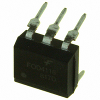
FOD4118
Description
TRIAC DRIVER ZERO CROSS 6-DIP
Manufacturer
Fairchild Semiconductor
Datasheet
1.FOD4108.pdf
(12 pages)
Specifications of FOD4118
Voltage - Isolation
5000Vrms
Number Of Channels
1
Voltage - Off State
800V
Output Type
AC, Triac, Zero Cross
Current - Gate Trigger (igt) (max)
1.3mA
Current - Hold (ih)
200µA
Current - Dc Forward (if)
30mA
Current - Output / Channel
300mA
Mounting Type
Through Hole
Package / Case
6-DIP (0.300", 7.62mm)
Output Device
PhotoTriac
Isolation Voltage
5 KV
Peak Output Voltage (vdrm)
800 V
Maximum Input Voltage
1.5 V
Maximum Output Voltage
560 VAC
Minimum Trigger Current
0.65 mA (Typ)
Configuration
1
Maximum Continuous Output Current
300 mA
Maximum Input Current
30 mA
Maximum Operating Temperature
+ 100 C
Maximum Power Dissipation
500 mW
Maximum Reverse Diode Voltage
6 V
Maximum Turn-on Time
60 us
Minimum Operating Temperature
- 55 C
Typical Input Voltage
1.25 V
Zero-crossing Circuit
Yes
Zero-crossing Voltage
25 V
Lead Free Status / RoHS Status
Lead free / RoHS Compliant
Available stocks
Company
Part Number
Manufacturer
Quantity
Price

Part Number:
FOD4118SD
Manufacturer:
FAIRCHILD/ن»™ç«¥
Quantity:
20 000


©2004 Fairchild Semiconductor Corporation
FOD410, FOD4108, FOD4116, FOD4118 Rev. 1.5.0
Electrical Characteristics
Zero Crossing Characteristics
Isolation Characteristics
*Typical values at T
Notes:
2. Test voltage must be applied within dv/dt rating.
3. All devices are guaranteed to trigger at an I
4. This is static dv/dt. See Figure 11 for test circuit. Commutating dv/dt is a function of the load-driving thyristor(s) only.
5. Isolation voltage, V
Typical Application
Typical circuit for use when hot line switching is required.
In this circuit the “hot” side of the line is switched and the
load connected to the cold or neutral side. The load may
be connected to either the neutral or hot line.
Symbol
Symbol
I
max I
and Pins 4, 5 and 6 are common.
F
I
V
V
DRM2
lies between max I
ISO
INH
F
V
(60mA).
CC
Input-Output Isolation
Voltage
Inhibit Voltage (MT1-MT2 voltage
above which device will not trigger)
Leakage in Inhibited State
* For highly inductive loads (power factor < 0.5), change this value to 360 ohms.
A
Characteristics
= 25°C
DC Characteristics
ISO
R
FT
in
, is an internal device dielectric breakdown rating. For this test, Pins 1, 2 and 3 are common,
(2mA for FOD410 and FOD4108 and 1.3mA for FOD4116 and FOD4118 and the absolute
1
2
3
Figure 1. Hot-Line Switching Application Circuit
(T
FOD4108
FOD4116
FOD4118
FOD410
A
= 25°C Unless otherwise specified) (Continued)
f = 60Hz, t = 1 min.
F
value less than or equal to max I
Test Conditions
330
I
I
Rated V
F
F
6
5
4
= Rated I
= Rated I
Test Conditions
4
360
DRM
R
part, 2mA for FOD410 and FOD4108, 1.3mA for
FOD4116 and FOD4118. The 39
capacitor are for snubbing of the triac and may or may
not be necessary depending upon the particular triac
and load use.
(5)
in
FT
FT
, off state
is calculated so that I
,
FKPF12N80
Min.
5000
FT
. Therefore, recommended operating
Min.
F
39*
0.01 F
Typ.*
is equal to the rated I
LOAD
Typ.*
20
8
resistor and 0.01µF
Max.
HOT
NEUTRAL
240 VAC
Max.
200
25
www.fairchildsemi.com
Vac(rms)
FT
Units
Units
of the
µA
V
Related parts for FOD4118
Image
Part Number
Description
Manufacturer
Datasheet
Request
R

Part Number:
Description:
Fairchild Semiconductor [IGBT MODULE]
Manufacturer:
Fairchild Semiconductor
Datasheet:

Part Number:
Description:
Discrete Semiconductor Modules
Manufacturer:
Fairchild Semiconductor
Part Number:
Description:
Discrete Semiconductor Modules
Manufacturer:
Fairchild Semiconductor
Part Number:
Description:
This N-Channel MOSFET is produced using Fairchild Semiconductor’s advanced Power Trench® process
Manufacturer:
Fairchild Semiconductor
Datasheet:
Part Number:
Description:
This N-Channel MOSFET is produced using Fairchild Semiconductor’s advanced Power Trench® process
Manufacturer:
Fairchild Semiconductor
Datasheet:
Part Number:
Description:
This N-Channel MOSFET is produced using Fairchild Semiconductor’s advanced PowerTrench® process
Manufacturer:
Fairchild Semiconductor
Datasheet:
Part Number:
Description:
This N-Channel MOSFET is produced using Fairchild Semiconductor’s advanced PowerTrench® process
Manufacturer:
Fairchild Semiconductor
Datasheet:
Part Number:
Description:
This N-Channel MOSFET is produced using Fairchild Semiconductor’s advanced Power Trench® process
Manufacturer:
Fairchild Semiconductor
Datasheet:
Part Number:
Description:
This N-Channel logic Level MOSFETs are produced using Fairchild Semiconductor‘s advanced Power Trench® process that has been special tailored to minimize the on-state resistance and yet maintain superior switching performance
Manufacturer:
Fairchild Semiconductor
Datasheet:
Part Number:
Description:
This N-Channel MOSFET is produced using Fairchild Semiconductor’s advanced Power Trench® process
Manufacturer:
Fairchild Semiconductor
Datasheet:
Part Number:
Description:
This N-Channel SyncFET™ is produced using Fairchild Semiconductor’s advanced PowerTrench® process
Manufacturer:
Fairchild Semiconductor
Datasheet:
Part Number:
Description:
This N-Channel SyncFET™ is produced using Fairchild Semiconductor’s advanced PowerTrench® process
Manufacturer:
Fairchild Semiconductor
Datasheet:
Part Number:
Description:
This N-Channel SyncFET™ is produced using Fairchild Semiconductor’s advanced PowerTrench® process
Manufacturer:
Fairchild Semiconductor
Datasheet:
Part Number:
Description:
This N-Channel logic Level MOSFETs are produced using Fairchild Semiconductor‘s advanced Power Trench® process that has been special tailored to minimize the on-state resistance and yet maintain superior switching performance
Manufacturer:
Fairchild Semiconductor
Datasheet:
Part Number:
Description:
This N-Channel MOSFET is produced using Fairchild Semiconductor’s advanced Power Trench® process that has been especially tailored to minimize the on-state resistance and yet maintain superior switching performance
Manufacturer:
Fairchild Semiconductor
Datasheet: