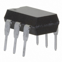
IL440-6 Vishay, IL440-6 Datasheet - Page 3

IL440-6
Manufacturer Part Number
IL440-6
Description
OPTOCP PHOTOTRIAC 400V 5MA 6DIP
Manufacturer
Vishay
Datasheet
1.IL440-4.pdf
(5 pages)
Specifications of IL440-6
Isolation Voltage
5300 Vrms
Voltage - Isolation
5300Vrms
Number Of Channels
1
Voltage - Off State
400V
Output Type
AC, Triac, Standard
Current - Gate Trigger (igt) (max)
5mA
Current - Hold (ih)
1mA
Current - Dc Forward (if)
60mA
Current - Output / Channel
100mA
Mounting Type
Through Hole
Package / Case
6-DIP (0.300", 7.62mm)
Configuration
1
Maximum Continuous Output Current
100 mA
Maximum Input Current
60 mA
Maximum Operating Temperature
+ 100 C
Maximum Power Dissipation
330 mW
Maximum Reverse Diode Voltage
5 V
Minimum Operating Temperature
- 40 C
Typical Input Voltage
1.25 V
Zero-crossing Circuit
No
Output Device
Triac
Peak Output Voltage (vdrm)
400 V
Maximum Output Voltage
280 VAC
Minimum Trigger Current
5 mA (Max)
No. Of Channels
1
Optocoupler Output Type
Phototriac
Input Current
50mA
Output Voltage
400V
Opto Case Style
DIP
No. Of Pins
6
Forward Voltage
1.6V
Lead Free Status / RoHS Status
Lead free / RoHS Compliant
Available stocks
Company
Part Number
Manufacturer
Quantity
Price
Company:
Part Number:
IL440-6
Manufacturer:
INFINEON
Quantity:
5 510
Notes
(1)
(2)
Notes
(1)
(2)
Document Number: 83631
Rev. 1.9, 29-Oct-10
ELECTRICAL CHARACTERISTICS
PARAMETER
Input
Forward voltage
Reverse voltage
Junction capacitance
Output
Off-state voltage
Peak on-state voltage
Trigger current 1
Trigger current 2
Trigger current 3
Critical rate of rise of off-state voltage
Critical rate of rise of on-state current
commutation
Coupler
Holding current
MAXIMUM SAFETY RATINGS
PARAMETER
INPUT
Forward voltage
OUTPUT
Power dissipation
SAFETY AND INSULATION RATINGS
PARAMETER
Climatic classification
(according to IEC68 part 1)
Pollution degree
Comparative tracking index
V
V
Insulation resistance at 25 °C
Insulation resistance at T
Insulation resistance at 100 °C
Partial discharge test voltage
P
I
T
SI
Minimum and maximum values are testing requirements. Typical values are characteristics of the device and are the result of engineering
evaluation. Typical values are for information only and are not part of the testing requirements.
Off-state output terminal voltage (see table 1.)
According to DIN EN 60747-5-5. This optocoupler is suitable for safe electrical isolation only within the safety ratings. Compliance with the
safety ratings shall be ensured by means of suitable protective circuits.
The device is used for protective separation agains electrical shock within the maximum safety ratings. This must be ensured by protective
circuits in the applications.
SI
IOTM
IORM
SO
(2)
(2)
S
For technical questions, contact:
TEST CONDITION
Optocoupler, Phototriac Output, Low
I
I
TM
F
(1)
V
TEST CONDITION
I
F
= 30 mA, V
V
pd
I
V
TEST CONDITION
= 100 mA, I
F
T
= 0, V
DIN VDE 0109
R
≥ 10 mA, V
= 6 V, R
V
V
V
= V
I
Method a,
= 0 V, f = 1 MHz
DRM
IO
IO
IO
(1)
I
I
F
R
IORM
= 500 V
= 500 V
= 500 V
= 50 mA
D
= 10 μA
(T
= 500 nA
= 0.67 V
amb
D
L
x 1.875
FT
= 150 Ω
= 60 V
S
= 30 mA
Input Current
≥ 3 V
= 25 °C, unless otherwise specified)
DRM
RMS
optocoupleranswers@vishay.com
IL440-4
IL440-5
IL440-6
IL440-4
IL440-5
IL440-6
P
SYMBOL
PART
SYMBOL
I
S, OUTPUT
S, INPUT
CTI
R
R
R
V
pd
IS
IS
IS
SYMBOL
dV/dt
V
dV/dt
D(RMS)
V
I
I
I
V
V
FT1
FT2
FT3
C
I
TM
H
R
F
j
crq
cr
MIN.
MIN.
8000
175
890
MIN.
0.13
400
400
400
5
Vishay Semiconductors
55/100/21
TYP.
TYP.
2
TYP.
1.25
0.25
1.5
50
15
10
50
5
1
≥ 10
≥ 10
MAX.
MAX.
≥ 10
1669
MAX.
130
300
500
250
175
3
12
11
9
www.vishay.com
UNIT
IL440
V/μs
V/μs
mA
pF
V
V
V
V
V
V
V
V
V
UNIT
UNIT
V
V
V
mW
mW
mA
mA
°C
peak
peak
peak
Ω
Ω
Ω
3


