KP-FSD3 Panduit Corp, KP-FSD3 Datasheet - Page 575
KP-FSD3
Manufacturer Part Number
KP-FSD3
Description
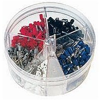
KIT FERRULE INS DIN AWG12-6
Manufacturer
Panduit Corp
Series
Pan-Term®r
Type
Ferrule Kitr
Datasheet
1.KP-FSD1.pdf
(1040 pages)
Specifications of KP-FSD3
Kit Type
Ferrule - Wire End
Values
100 pcs - Assorted Insulated 12 ~ 6 AWG Ferrules
Kit Contents
50 Pieces Of FSD81-10, 20 Pieces Each Of FSD82-12 And FSD83-12, 10 Pieces Of FSD84-12
Mounting Method
Crimp
Where Used
To terminate stranded wire for insertion into terminal blocks
Lead Free Status / Rohs Status
Lead free / RoHS Compliant


For applicator information, see page D1.143.
Type PN-R
• Continuously molded design provides reliable, consistent
• Ring tongue design assures a secure connection in high
• Metal insulation grip sleeve crimps to wire insulation, providing
Part Number System for Reel Smart
Part Number
PN18-4R-3K
PN18-6RN-3K
PN18-6R-3K
PN18-8R-3K
PN18-10R-3K
PN18-14R-3K
PN14-4R-3K
PN14-6RN-3K
PN14-6R-3K
PN14-8R-3K
PN14-10R-3K
PN14-14R-3K
PN10-6R-2K
PN10-8R-2K
PN10-10R-2K
PN10-14R-2K
PN10-56R-2K
PN10-38R-2K
Type
P = Terminal
BS = Butt Splice
performance through the applicator for a high quality termination
every time
vibration applications
protection to the crimp joint during high vibration applications
P
Ring Terminals, Nylon Insulated – Non-Funnel Entry
N = Nylon
NF = Nylon
V = Vinyl
22 – 18
16 – 14
12 – 10
Range
AWG
AWG
AWG
Wire
Insulation
Insulated
Insulated
Funnel
Entry
Insulated
NF
Yellow
Color
Code
Blue
Red
18 = #22 – 18
14 = #16 – 14
12 = #16 – 12
10 = #12 – 10
Wire Range
Thickness
For technical assistance in the U.S., call 866-405-6654 (outside the U.S., see inside back cover for directory)
Stock
14
(In.)
0.03
0.03
0.04
—
0.145
0.162
0.225
Max.
(In.)
Ins.
ELECTRICAL SOLUTIONS
Stud Size
4 = #4
5 = #5
6 = #6
8 = #8
10 = #10
14 = 1/4"
56 = 5/16"
38 = 3/8"
™
Terminals
6
5/16"
Stud
Size
1/4"
1/4"
1/4"
3/8"
#10
#10
#10
#4
#6
#6
#8
#4
#6
#6
#8
#6
#8
Tongue Configuration
R
HDR = Heavy
F
FF
LF
SLF = Short
• Internal barrel serrations assure good wire contact and maximum
• UL Flammability UL 94V-2/HB, maximum insulation temperature
• UL and CSA rated up to 600 V per UL 486A/B
tensile strength
221°F (105°C)
C
0.80
0.74
0.78
0.86
0.86
1.05
0.76
0.76
0.86
0.86
0.86
1.06
1.06
1.06
1.06
1.21
1.21
1.29
= Locking
L
= Ring
= Fork
= Fanged
Fork
Locking
Fork
Figure Dimension
Duty
Ring
Fork
L
R
(In.)
0.25
0.22
0.25
0.31
0.31
0.45
0.25
0.25
0.31
0.31
0.31
0.44
0.38
0.38
0.38
0.52
0.52
0.58
W
W
0.22
0.18
0.22
0.25
0.25
0.38
0.22
0.22
0.25
0.25
0.25
0.38
0.31
0.31
0.31
0.38
0.38
0.43
C
N = Narrow
W = Wide
B = Butted
= Standard
Configuration
Tongue
Tongue
Seam
(leave blank)
Crimp Die
Special
CD9-1A
CD9-2A
CD9-3B
Series
CA9
N
CA-800/EZ
Crimp Die
CD-800-1
CD-800-2
CD-800-3
Series
2K = 2,000 pcs.
3K = 3,000 pcs.
Std. Pkg. Size
3K
Pieces
3000
3000
3000
3000
3000
3000
3000
3000
3000
3000
3000
3000
2000
2000
2000
2000
2000
2000
Reel
Per
D1.103
Management
Identification
Accessories
Connectors
Connectors
Grounding
Pre-Printed
& Write-On
Protection
Permanent
Solutions
Cable Ties
Terminals
Lockout/
Overview
Steel Ties
& Safety
Stainless
Raceway
Abrasion
Labeling
Systems
Surface
Markers
Tagout
System
Wiring
Labels
Power
Cable
Cable
Index
Duct
E5.
B1.
B2.
B3.
D1.
D2.
D3.
C1.
C2.
C3.
C4.
E1.
E2.
E3.
E4.
A.
F.