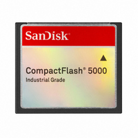
SDCFCF-001G-388 SanDisk, SDCFCF-001G-388 Datasheet - Page 34

SDCFCF-001G-388
Manufacturer Part Number
SDCFCF-001G-388
Description
COMPACT FLASH IND 1GB FIXED
Manufacturer
SanDisk
Type
CompactFlashr
Datasheet
1.SDCFCF-001G-388.pdf
(97 pages)
Specifications of SDCFCF-001G-388
Memory Size
1GB
Memory Type
CompactFLASH
Density
1GByte
Operating Supply Voltage (typ)
3.3/5V
Operating Temperature (min)
0C
Operating Temperature (max)
70C
Package Type
Not Required
Mounting
Desktop
Pin Count
50
Operating Temperature Classification
Commercial
Operating Supply Voltage (min)
3.135/4.5V
Operating Supply Voltage (max)
3.465/5.5V
Programmable
Yes
Lead Free Status / RoHS Status
Lead free / RoHS Compliant
SanDisk Industrial Grade CompactFlash 5000
PIO Data Transfers
Figure 10 defines the relationships between the interface signals for PIO data
transfers. For PIO Modes 3 and above the minimum value of t
Word 68 in the IDENTIFY DEVICE parameter list. Table 22defines the
minimum value that will be placed in Word 68.
Notes: 1)
The PIO data transfer parameters are defined in Table 22: PIO Data Transfer
to/from Device.
Note: SanDisk CompactFlash Memory cards do not assert an -IORDY signal.
a. t0 is the minimum total cycle time, t2 is the minimum command active
© 2007 SanDisk® Corporation
t0 a
t1
t2 a
t2ia
t3
t4
t5
t6
t6a b
t9
time, and t2i is the minimum command recovery time or command
inactive time. The actual cycle time equals the sum of the actual command
active time and the actual command inactive time. The three timing
requirements of t0, t2, and t2i shall be met. The minimum total cycle time
requirements are greater than the sum of t2 and t2i. This means a host
2)
Cycle time (min.)
Address valid to IORD-/IOWR- setup
(min.)
IORD-/IOWR- pulse width 16-bit (min.)
IORD-/IOWR- recovery time (min.)
IOWR- data setup (min.)
IOWR- data hold (min.)
IORD- data setup (min.)
IORD- data hold (min.)
IORD- data tri-state (max.)
IORD-/IOWR- to address valid hold
(min.)
Device address consists of signals -CS0, -CS1 and -DA(2:0).
Data consists of DD(15:0).
PIO Timing Parameters
Table 22: PIO Data Transfer to/from Device
Figure 10: PIO Data Transfer to/from Device
27
Mode 0
(ns)
600
165
70
60
30
50
30
20
5
Mode 1
(ns)
383
125
50
45
20
35
30
15
5
Mode 2
(ns)
240
100
30
30
15
20
30
10
5
Mode 3
0
(ns)
180
30
80
70
30
10
20
30
10
is specified by
5
Product Manual
Mode 4
(ns)
120
July 2007
25
70
25
20
10
20
30
10
5


