HYS72T128000HR-3S-B Qimonda, HYS72T128000HR-3S-B Datasheet - Page 27
HYS72T128000HR-3S-B
Manufacturer Part Number
HYS72T128000HR-3S-B
Description
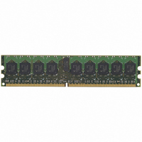
MODULE DDR2 1GB 240-DIMM
Manufacturer
Qimonda
Datasheet
1.HYS72T128000HR-3S-B.pdf
(52 pages)
Specifications of HYS72T128000HR-3S-B
Memory Type
DDR2 SDRAM
Memory Size
1GB
Speed
333MHz
Package / Case
240-DIMM
Lead Free Status / RoHS Status
Lead free / RoHS Compliant
Other names
675-1028


2) ODT turn off time min. is when the device starts to turn off ODT resistance. ODT turn off time max is when the bus is in high impedance.
3.4
List of tables defining
•
•
•
Rev. 1.2, 2007-01
03292006-JXZQ-CG6T
Parameter
Operating Current 0
One bank Active - Precharge;
valid commands. Address and control inputs are SWITCHING, Databus inputs are SWITCHING.
Operating Current 1
One bank Active - Read - Precharge;
t
control inputs are SWITCHING, Databus inputs are SWITCHING.
Precharge Standby Current
All banks idle; CS is HIGH; CKE is HIGH;
Databus inputs are SWITCHING.
Precharge Power-Down Current
Other control and address inputs are STABLE, Data bus inputs are FLOATING.
Precharge Quiet Standby Current
All banks idle; CS is HIGH; CKE is HIGH;
Data bus inputs are FLOATING.
Active Standby Current
Burst Read: All banks open; Continuous burst reads; BL = 4; AL = 0, CL =
t
SWITCHING; Data Bus inputs are SWITCHING;
Active Power-Down Current
All banks open;
are FLOATING. MRS A12 bit is set to LOW (Fast Power-down Exit);
Active Power-Down Current
All banks open;
are FLOATING. MRS A12 bit is set to HIGH (Slow Power-down Exit);
Operating Current - Burst Read
All banks open; Continuous burst reads; BL = 4; AL = 0, CL =
t
bus inputs are SWITCHING;
Operating Current - Burst Write
All banks open; Continuous burst writes; BL = 4; AL = 0, CL =
t
SWITCHING; Data Bus inputs are SWITCHING;
RCD
RAS
RP
RAS
Table 18 “IDD Measurement Conditions” on Page 27
Table 21 “IDD Specification for HYS72T[64/128/256]xxxHR–3.7–B” on Page 30
Table 22 “IDD Specification for HYS72T[64/128/256]xxxHR–5–B” on Page 31
Both are measured from
12.5 ns (= 2.5 x 5 ns) after the clock edge that registered a first ODT HIGH if
=
=
=
=
t
RPMIN
t
t
t
RAS.MAX
RAS.MAX.
RCD.MIN
; CKE is HIGH, CS is HIGH between valid commands; Address inputs are SWITCHING; Data
, AL = 0, CL =
,
,
t
t
t
t
RP
CK
CK
RP
=
=
=
=
I
t
t
t
I
t
RP.MIN
CK.MIN
CK.MIN
RP.MAX
DD
DD
Specifications and Conditions.
t
AOFD
; CKE is HIGH, CS is HIGH between valid commands. Address inputs are
, CKE is LOW; Other control and address inputs are STABLE, Data bus inputs
, CKE is LOW; Other control and address inputs are STABLE, Data bus inputs
Specifications and Conditions
; CKE is HIGH, CS is HIGH between valid commands. Address inputs are
CL
I
. Both are measured from
t
OUT
CK
MIN
=
= 0mA.
; CKE is HIGH, CS is HIGH between valid commands. Address and
t
CK.MIN
I
OUT
t
,
CK
t
t
= 0 mA, BL = 4,
RC
CK
=
=
=
t
CK.MIN
t
t
RC.MIN
CK.MIN
I
OUT
; Other control and address inputs are SWITCHING,
t
,
; Other control and address inputs are STABLE,
AOFD
= 0 mA.
t
RAS
, which is interpreted differently per speed bin. For DDR2-400/533,
=
t
CK
t
27
RAS.MIN
CL
=
CL
t
CK.MIN
MIN
MIN
, CKE is HIGH, CS is HIGH between
;
;
t
t
CK
CK
,
t
t
CK
RC
=
=
= 5 ns.
CL
t
t
=
CKMIN
CK.MIN
t
MIN
RC.MIN
HYS72T[64/128/256]xxxHR–[3S/3.7/5]–B
;
;
;
t
t
RAS
CK
,
t
RAS
=
240-Pin Registered DDR2 SDRAM
=
t
CK.MIN
t
RASMAX
=
I
DD
t
RAS.MIN
;
Measurement Conditions
;
,
Internet Data Sheet
Symbol Note
I
I
I
I
I
I
I
I
I
I
DD0
DD1
DD2N
DD2P
DD2Q
DD3N
DD3P(0)
DD3P(1)
DD4R
DD4W
TABLE 18
1)2)3)4)5)
—
6)
—
—
—
—
—
—
6)
—
t
AOFD
is
Related parts for HYS72T128000HR-3S-B
Image
Part Number
Description
Manufacturer
Datasheet
Request
R

Part Number:
Description:
BGA
Manufacturer:
Qimonda
Datasheet:
Part Number:
Description:
BGA
Manufacturer:
Qimonda
Datasheet:
Part Number:
Description:
Manufacturer:
Qimonda
Datasheet:
Part Number:
Description:
Manufacturer:
Qimonda
Datasheet:
Part Number:
Description:
DDR2 16Mx16, 667MHz, FBGA84, leadfree
Manufacturer:
Qimonda
Datasheet:
Part Number:
Description:
DDR2 32Mx16, 533MHz, FBGA84, leadfree
Manufacturer:
Qimonda
Datasheet:

Part Number:
Description:
HYB18TC1G160BF-3.71-Gbit DDR2 SDRAM
Manufacturer:
QIMONDA Qimonda AG
Datasheet:
Part Number:
Description:
HYB18TC1G800BF-3S1-Gbit DDR2 SDRAM
Manufacturer:
QIMONDA Qimonda AG
Datasheet: