MT4VDDT3264HY-335F2 Micron Technology Inc, MT4VDDT3264HY-335F2 Datasheet - Page 21
MT4VDDT3264HY-335F2
Manufacturer Part Number
MT4VDDT3264HY-335F2
Description
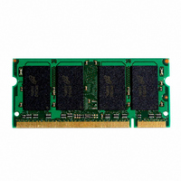
MODULE DDR 256MB 200-SODIMM
Manufacturer
Micron Technology Inc
Specifications of MT4VDDT3264HY-335F2
Memory Type
DDR SDRAM
Memory Size
256MB
Speed
333MT/s
Package / Case
200-SODIMM
Main Category
DRAM Module
Sub-category
DDR SDRAM
Module Type
200SODIMM
Device Core Size
64b
Organization
32Mx64
Total Density
256MByte
Chip Density
512Mb
Access Time (max)
700ps
Maximum Clock Rate
333MHz
Operating Supply Voltage (typ)
2.5V
Operating Current
780mA
Number Of Elements
4
Operating Supply Voltage (max)
2.7V
Operating Supply Voltage (min)
2.3V
Operating Temp Range
0C to 70C
Operating Temperature Classification
Commercial
Pin Count
200
Mounting
Socket
Lead Free Status / RoHS Status
Lead free / RoHS Compliant
Other names
557-1231
MT4VDDT3264HY-335F2
MT4VDDT3264HY-335F2


pdf: 09005aef8086ea3d, source: 09005aef8086ea0b
DD4C8_16_32x64HG.fm - Rev. C 9/04 EN
30.
31. READs and WRITEs with auto precharge are not
32. Any positive glitch in the nominal voltage must be
33. Normal Output Drive Curves:
160
140
120
100
80
60
40
20
Figure 9: Pull-Down Characteristics
0
0.0
t
minimum actually applied to the device CK and
CK/ inputs, collectively during device bank active.
allowed to be issued until
fied prior to the internal precharge command
being issued.
less than 1/3 of the clock and not more than
+400mV or 2.9V maximum, whichever is less. Any
negative glitch must be less than 1/3 of the clock
cycle and not exceed either -300mV or 2.2V mini-
mum, whichever is more positive.
d. The variation in driver pull-up current within
a. The full variation in driver pull-down current
b. The variation in driver pull-down current
c. The full variation in driver pull-up current
HP min is the lesser of
from minimum to maximum process, temper-
ature and voltage will lie within the outer
bounding lines of the V-I curve of Figure 9,
Pull-Down Characteristics.
within nominal limits of voltage and tempera-
ture is expected, but not guaranteed, to lie
within the inner bounding lines of the V-I
curve of Figure 9, Pull-Down Characteristics.
from minimum to maximum process, temper-
ature and voltage will lie within the outer
bounding lines of the V-I curve of Figure 10,
Pull-Up Characteristics.
nominal limits of voltage and temperature is
expected, but not guaranteed, to lie within the
inner bounding lines of the V-I curve of Figure
10, Pull-Up Characteristics.
0.5
1.0
V
V
OUT
OUT
(V)
(V)
t
t
CL minimum and
RAS(MIN) can be satis-
1.5
2.0
Minimum
t
CH
2.5
21
34. Reduced Output Drive Curves:
64MB, 128MB, 256MB (x64, SR)
-100
-120
-140
-160
-180
-200
-20
-40
-60
-80
0
200-PIN DDR SDRAM SODIMM
Figure 10: Pull-Up Characteristics
b. The variation in driver pull-down current
d. The variation in driver pull-up current within
0.0
a. The full variation in driver pull-down current
e. The full variation in the ratio of the maximum
c. The full variation in driver pull-up current
f. The full variation in the ratio of the nominal
Micron Technology, Inc., reserves the right to change products or specifications without notice.
to minimum pull-up and pull-down current
should be between 0.71 and 1.4, for device
drain-to-source voltages from 0.1V to 1.0V, and
at the same voltage and temperature.
pull-up to pull-down current should be unity
±10 percent, for device drain-to-source volt-
ages from 0.1V to 1.0V.
from minimum to maximum process, temper-
ature and voltage will lie within the outer
bounding lines of the V-I curve of Figure 11,
Reduced Output Pull-Down Characteristics,
on page 22.
within nominal limits of voltage and tempera-
ture is expected, but not guaranteed, to lie
within the inner bounding lines of the V-I
curve of Figure 11, Reduced Output Pull-Down
Characteristics, on page 22.
from minimum to maximum process, temper-
ature and voltage will lie within the outer
bounding lines of the V-I curve of Figure 12,
Reduced Output Pull-Up Characteristics, on
page 22.
nominal limits of voltage and temperature is
expected, but not guaranteed, to lie within the
inner bounding lines of the V-I curve of
Figure 12, Reduced Output Pull-Up Character-
istics, on page 22.
0.5
1.0
V
DD
Q - V
©2004 Micron Technology, Inc. All rights reserved.
OUT
(V)
1.5
2.0
2.5
Related parts for MT4VDDT3264HY-335F2
Image
Part Number
Description
Manufacturer
Datasheet
Request
R

Part Number:
Description:
IC SDRAM 64MBIT 133MHZ 54TSOP
Manufacturer:
Micron Technology Inc
Datasheet:

Part Number:
Description:
IC SDRAM 64MBIT 5.5NS 86TSOP
Manufacturer:
Micron Technology Inc
Datasheet:
Part Number:
Description:
IC SDRAM 64MBIT 200MHZ 86TSOP
Manufacturer:
Micron Technology Inc
Datasheet:
Part Number:
Description:
IC SDRAM 64MBIT 133MHZ 54TSOP
Manufacturer:
Micron Technology Inc
Datasheet:
Part Number:
Description:
IC SDRAM 128MBIT 133MHZ 54TSOP
Manufacturer:
Micron Technology Inc
Datasheet:

Part Number:
Description:
IC SDRAM 256MBIT 133MHZ 90VFBGA
Manufacturer:
Micron Technology Inc
Datasheet:
Part Number:
Description:
IC SDRAM 128MBIT 133MHZ 54TSOP
Manufacturer:
Micron Technology Inc
Datasheet:
Part Number:
Description:
IC SDRAM 256MBIT 133MHZ 54TSOP
Manufacturer:
Micron Technology Inc
Datasheet:

Part Number:
Description:
IC DDR SDRAM 512MBIT 6NS 66TSOP
Manufacturer:
Micron Technology Inc
Datasheet:
Part Number:
Description:
IC SDRAM 128MBIT 167MHZ 86TSOP
Manufacturer:
Micron Technology Inc
Datasheet:
Part Number:
Description:
IC SDRAM 128MBIT 143MHZ 86TSOP
Manufacturer:
Micron Technology Inc
Datasheet:

Part Number:
Description:
SDRAM 256M-BIT 1.8V 54-PIN VFBGA
Manufacturer:
Micron Technology Inc
Datasheet:
Part Number:
Description:
IC SDRAM 128MBIT 143MHZ 86TSOP
Manufacturer:
Micron Technology Inc
Datasheet:

Part Number:
Description:
IC SDRAM 128MBIT 125MHZ 54VFBGA
Manufacturer:
Micron Technology Inc
Datasheet:
Part Number:
Description:
IC SDRAM 128MBIT 125MHZ 54VFBGA
Manufacturer:
Micron Technology Inc
Datasheet: