27969 Parallax Inc, 27969 Datasheet - Page 15
27969
Manufacturer Part Number
27969
Description
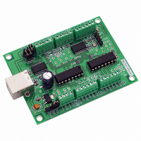
BOARD BISTEP MOTOR CTRLR USB
Manufacturer
Parallax Inc
Datasheet
1.27969.pdf
(21 pages)
Specifications of 27969
Motor Type
Stepper, Unipolar
Number Of Motors
2
Voltage - Output
15V
Voltage - Logic Supply
6.5 V ~ 15 V
Current - Output
1A
Termination Style
Screw Terminal
Product
Microcontroller Accessories
Lead Free Status / RoHS Status
Lead free / RoHS Compliant
For Use With
27964 - UNIPOLAR STEPPER MOTOR 12VDC
Lead Free Status / RoHS Status
Lead free / RoHS Compliant, Lead free / RoHS Compliant


Common Parallax Stamp Issue Summary
First Use
Use a linear power supply, not a switching power supply.
Make sure your power supply is large enough to meet the demands of your
application.
Keep your leads between the two units short.
We suggest running communications at 9600 baud.
Re-issue the ‘H’ command on current regulating boards after reset or power-
cycling
Use of a linear power supply (as opposed to a switching power supply) is a very strong
recommendation. Switchers generally do not have the short-term power reserves needed to handle the
extreme variances in power demanded on motor startups, and they are usually much "noisier" from an
electrical point of view. We have had no reported power-supply related problems when our customers
use linear supplies of adequate size; we have had frequent issues when switchers are used. For
example, switchers will often have 10-20% of “ripple” in their voltage (i.e., there will be a periodic
variance of several volts in their supplied power, usually at the power line frequency of 50 or 60 hz).
This means that the motors are “feeling” a 10-20% variance in their drive power, which means that
microstepping will be unreliable in position.
We have frequently had customers complain that their motor stalls or does not appear to have enough
power. In most cases, this has been traced to the customer having selected a power supply that can
only deliver about 1/2 of the current required by the motor. Remember that a stepper motor can have 2
windings on at a given time; this means that it can draw twice as much current as you would expect,
referring only to the current rating of the motor. Please refer to our “Universal Stepper” manual
section
the current requirements for your application.
Even though we have we have successfully operated via TTL serial at distances of up to 26 feet, TTL
signals are only "clean" (that is to say, little "bounce" or induced voltages) at up to 3 feet.
quite susceptible to induced voltages from antenna effects, impedance matching issues, and from
neighboring signals. In general, when the signals are kept to under 3 feet, the amount of induced
signals are too small to cause a logic circuit to trigger (unless they are routed beside a motor driver
line).
signals.
When operating using TTL-Serial mode (as opposed to RS232 serial, which uses much larger voltages)
on a 26 foot cable, we have found that there can be about a 0.1 microsecond wide 5 volt spike induced
onto one signal line when a neighboring signal line changes state (i.e., when a serial bit is sent to our
board, a narrow spike can be induced on the serial output line from our board to your stamp). Due to
the nature of the serial timing between the products, this spike is normally ignored under serial I/O (our
firmware rejects it via a digital filter, and the timing of serial I/O to and from the stamp is such that the
stamp would not see it). Our suggestion of 3 feet or less avoids this potential issue.
The most recent versions of the firmware (GenStepper versions 1.65 and above) have enough idle time
built into it when operating in the suggested modes for Stamp communications that you should have no
problems. Operate at 2400 baud only if you cannot get reliable operation at 9600 baud (and please
contact us for further assistance in this case).
If you are using any of the current regulating series of boards (the BC2D15, BC4D15, or the UCC30xx
series), remember to re-issue the appropriate “H” command at any time that the board is reset or
power-cycled. Otherwise, the board will operate at its default power-on level, which is usually full-
power; this may damage your motor if it is more than 1.5 to 2 times the recommended current for the
particular motor! Please see the manual for your specific board and firmware for documentation about
the “H” command.
“Calculating Motor Current Requirements”
They also require a good ground reference between the boards which are transmitting the
for a more complete summary of how to calculate
Peter Norberg Consulting, Inc.
They are
Page 15
Related parts for 27969
Image
Part Number
Description
Manufacturer
Datasheet
Request
R


Part Number:
Description:
Microcontroller Modules & Accessories DISCONTINUED BY PARALLAX
Manufacturer:
Parallax Inc

Part Number:
Description:
BOOK UNDERSTANDING SIGNALS
Manufacturer:
Parallax Inc
Datasheet:


Part Number:
Description:
COMPETITION RING FOR SUMOBOT
Manufacturer:
Parallax Inc
Datasheet:
Part Number:
Description:
BOARD EXPERIMENT+LCD NX-1000
Manufacturer:
Parallax Inc
Datasheet:
Part Number:
Description:
IC MCU 2K FLASH 50MHZ SO-18
Manufacturer:
Parallax Inc
Datasheet:

Part Number:
Description:
Microcontroller Modules & Accessories AD592 Temperature Probe Sensor
Manufacturer:
Parallax Inc

Part Number:
Description:
ADC (A/D Converters) 8-bit ADC DIP ADC0831
Manufacturer:
Parallax Inc
Datasheet:

Part Number:
Description:
TEXT BASIC ANALOG & DIGITAL
Manufacturer:
Parallax Inc
Datasheet:

Part Number:
Description:
TEXT WHAT'S A MICROCONTROLLER
Manufacturer:
Parallax Inc
Datasheet:

Part Number:
Description:
IC ADC 12BIT 8CH MAX1270 24-DIP
Manufacturer:
Parallax Inc
Datasheet:

Part Number:
Description:
BASIC STAMP I MODULE
Manufacturer:
Parallax Inc
Datasheet:

Part Number:
Description:
BASIC STAMP II MODULE
Manufacturer:
Parallax Inc
Datasheet: