EXII-7710UC 3M, EXII-7710UC Datasheet
EXII-7710UC
Specifications of EXII-7710UC


Related parts for EXII-7710UC


EXII-7710UC Summary of contents
Page 1
... MicroTouch ™ Controller EX USB Reference Guide Formerly EX II 55xxUC now EX121 EX II 77xxUC now EX111 Read and understand all safety information contained in this document before using this product. 3M Touch Systems, Inc. Proprietary Information ™ 3 ...
Page 2
... Touch Systems, Inc. warranty, then 3M Touch Systems, Inc. sole obligation and User’s and Purchaser’s exclusive remedy, will be Touch Systems, Inc. option, to repair or replace that Product quantity or software media or to refund its purchase price. 3M Touch Systems, Inc. has no obligation under 3M Touch Systems, Inc. warranty for any Product, software or software media that has been modified or damaged through misuse, accident, neglect, or subsequent manufacturing operations or assemblies by anyone other than 3M Touch Systems, Inc ...
Page 3
... MicroTouch™ Controller EX USB Reference Guide Contents Chapter 1 Introduction What You Need to Know .......................................................................................... 5 Important Safety Information .................................................................................... 5 Sensor Care and Cleaning ......................................................................................... 6 3M Touch Systems Support Services........................................................................ 7 Contact 3M Touch Systems ...................................................................................... 7 Chapter 2 Integrating the 3M™ MicroTouch™ EX USB Controllers Overview of the EX USB Controllers ....................................................................... 9 Handling and ESD Protection ...
Page 4
... Controller ID Report 12 ............................................................................................ 25 Read Parameter Request 16....................................................................................... 27 Parameter Data Report 4 ........................................................................................... 28 Appendix A EX121 Controller Specifications EX121 Dimensions.................................................................................................... 29 Technical Specifications............................................................................................ 31 Physical Dimensions ................................................................................................. 31 Appendix B EX111 Controller Specifications Technical Specifications............................................................................................ 34 Physical Dimensions ................................................................................................. 34 3M™ MicroTouch™ Controller EX USB Reference Guide 3M Touch Systems, Inc. Proprietary Information ...
Page 5
... Touch Systems is committed to being a premier supplier in touch systems throughout the world Touch Systems customer, you are aware that we have strong internal programs that meet or exceed environmental regulations of our customers and the regions in which we conduct business. ...
Page 6
... Follow all instructions and recommendations in the manufacturer's Material Safety Data Sheet and product label. Sensor Care and Cleaning The sensor requires very little maintenance. 3M Touch Systems recommends that you periodically clean the glass surface. Typically, an isopropyl alcohol and water solution ratio of 50:50 is the best cleaning agent for your touch screen ...
Page 7
... Technical Support is available Monday through Friday 8:30 a.m. to 5:30 p.m. with limited call back service after 5:30 p.m. until 8:00 p.m. US Eastern Standard Time – p.m. throughout Europe. You can contact 3M Touch Systems Technical Support (US only -- Eastern Standard Time) by calling the hot line, sending email or a fax. • ...
Page 8
...
Page 9
... To integrate and test the EX USB controller, you need the following items: • A 3M™ MicroTouch™ surface capacitive sensor (available in a variety of sizes). 3M Touch Systems, Inc. Proprietary Information 9 ...
Page 10
... The controller will operate with the standard USB +5V bus power. • A touch driver and a calibration program. You can use 3M™ MicroTouch™ software which includes the necessary touch driver and utilities software. Handling and ESD Protection When mounting the sensor and controller, use normal precautions for handling electrostatic sensitive devices. The EX USB controllers have internal protection to ± ...
Page 11
... MicroTouch™ Controller EX USB Reference Guide Sensor Connection The sensor cable has a 12-pin ( dual row female connector that plugs into the EX121 controller. Table 2 describes the pins on this connector. The sensor connector always exits towards the USB cable. Table 2. Sensor Cable Connector for EX121 Controllers ...
Page 12
... Mounting the Sensor There are several methods for mounting the sensor depending on your application. If you need instructions or recommendations from 3M Touch Systems on how to incorporate a sensor into your design, refer to the 3M Guide (P/N 19-278). All 3M Touch Systems documentation is available from the corporate website at www ...
Page 13
... MicroTouch™ Controller EX USB Reference Guide The LED indicator also provides visual indication of the controller’s internal self-tests by flashing or blinking a code that may be interpreted using the table below. The test results are also returned as part of the USB Status report. Those bits that result in a flashing error code are repeated in the table below ...
Page 14
... Note 3: indicates that the EEPROM is not formatted when given by the ROM code Installing 3M™ MicroTouch™ Software 3M™ MicroTouch™ Software includes the driver that enables your sensor to work with your computer. 3M Touch Systems has touch drivers for many operating systems, including Windows Vista, XP, XP embedded, 2000, 9X, Windows Me, Windows CE, and Windows NT 4 ...
Page 15
... You should be aware of the results before executing any firmware commands. To optimize the performance of the 3M™ MicroTouch™ EX USB touch controller and simplify the development of custom drivers, 3M Touch Systems recommends you use the commands listed in this chapter for current development. Using these commands ensures compatibility with all 3M™ ...
Page 16
... MicroTouch™ USB controllers. Modifications of existing software should not be necessary when replacing an older controller. The following commands are those that 3M Touch Systems currently uses for communications. 3M Touch Systems recommends that you use only these commands for 3M™ MicroTouch™ EX USB controller communications. ...
Page 17
... MicroTouch™ Controller EX USB Reference Guide Sending Commands to the Controller Table 5. General Format for Vendor Requests Offset Field 0 bmRequestType 1 bRequest 2 wValue 4 wIndex 6 wLength The Type field should be set to Vendor (0x10). The Recipient field should be set to Device. The Direction field depends on the command. ...
Page 18
... Controller Initialization To initialize the EX USB controller, 3M Touch Systems recommends that the host system issue a Reset command whenever the host system is powered on and is attempting to establish communication with the controller. Coordinate Data Report 1 Coordinate Data Report 1 is used to transfer both the raw and adjusted coordinate data to the host ...
Page 19
... Because Report 1 sends touch data continually the most versatile mode, and it provides the best response time and overall feel. 3M Touch Systems recommends that the touch driver generate an event as each packet in the data stream arrives. Because touchdown and liftoff events are specially coded, your software can generate mouse events that correspond to what the user is doing ...
Page 20
... The Controller Status Request is used to poll the controller for command completion when a previous USB request involved a controller reset. Refer to the Reset Request 7 for additional details. 3M™ MicroTouch™ Controller EX USB Reference Guide ( (895, 96) (128, 671) 3M Touch Systems, Inc. Proprietary Information ...
Page 21
... MicroTouch™ Controller EX USB Reference Guide Table 9. Controller Status Request Offset The direction bit in bmRequestType has been set to 1 (device-to-host) to return the status report. The byte bRequest is set indicate that this is a Controller Status request. The controller does not use the wValue and wIndex fields. These fields should be set to zero to ensure future compatibility ...
Page 22
... Table 12. Touch Status Bit Number Async reports – the only active asynchronous report is the Touch Coordinate report 1. Extended POC Status – This is additional power on status information. This is a 2-byte bitmapped field. 3M™ MicroTouch™ Controller EX USB Reference Guide Size Value 2 0xXXXX 9 9 bytes ...
Page 23
... MicroTouch™ Controller EX USB Reference Guide Table 13. Extended POC Status Bit Number Reset Request 7 This is a request to perform a controller reset. The standard hard or soft reset can be requested. Soft resets are generally required for any parameter changes to take effect. A soft reset results in the touch application using its initial (start-up) values. ...
Page 24
... EX Controller Compatibility Issues The hard reset did not use a device disconnect as part of the reset process for the previous 3M™ MicroTouch™ USB controller. The disconnect causes the driver to unload and will result in any handles to the driver that an application may have becoming invalid. An application should handle an unplug event ...
Page 25
... MicroTouch™ Controller EX USB Reference Guide Controller ID Request 10 This is a request to send various pieces of information that identify the controller, including the controller type and firmware revision level. The key use for this request is in identifying the mode that the controller is running in and the revision level of the ASIC firmware ...
Page 26
... ASIC Type – this indicates the type and version of the ASIC in the controller. The value 0x0100 indicates the first EX revision. The high byte is used to note major ASIC changes, such as a new ASIC family, and the low byte indicates changes within a family. 3M™ MicroTouch™ Controller EX USB Reference Guide Size Value ...
Page 27
... MicroTouch™ Controller EX USB Reference Guide Read Parameter Request 16 This is a request to send the contents of a parameter via the control endpoint. This is a one-time transfer of data. The request is used to access data in the controller. This request provides a means for reading the configuration parameters. The request uses parameter numbers to determine what data is being requested and where that data is located ...
Page 28
... Data byte – At least 1 data byte will follow when data size is greater than zero. The number of data bytes returned by this report is limited by the “Max Param Write” value returned by the Controller ID report. The contents of this data section are dependent on which parameter is being accessed. 3M™ MicroTouch™ Controller EX USB Reference Guide Size Value 1 ...
Page 29
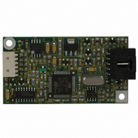
... MicroTouch™ Controller EX USB Reference Guide APPENDIX A EX121 Controller Specifications This section provides controller specifications such as power requirements, environmental requirements, and cable connectors. The EX121 controller is a compact (3.5 x 2.25 x 0.3 inches), USB controller. This controller can be internally mounted in your display, or enclosed in a molded plastic case (3 ...
Page 30
... The following figures show the overall dimensions of the EX121 controller and the locations of the mounting holes and connectors. Figure 1 EX121 Overall Dimensions Figure 2 Cased EX121 Touch Controller 3M™ MicroTouch™ Controller EX USB Reference Guide 3M Touch Systems, Inc. Proprietary Information ...
Page 31
... Technical Specifications The controller specifications listed below were validated in test systems containing 3M Touch Systems components. These specifications may not be valid if configured with components from suppliers other than 3M Touch Systems. All components in the manufacture of electronic controllers are RoHS Directive compliant (2002/95/EC). Physical Dimensions ...
Page 32
... Air Discharge * – Class 1 per section 9 of IEC 61000-4-2 Normal Operation – No false touches * ESD discharges Touch Systems sensor connected to the controller MTBF (by MIL Std. 217F Calculation) Touch System Parameters Accuracy vs. Dynamic Temperature Change (Tested at 0 deg deg. C with a 0.5 deg. C/minute temperature ramp) ...
Page 33
... MicroTouch™ Controller EX USB Reference Guide APPENDIX B EX111 Controller Specifications This section provides controller specifications such as power requirements, environmental requirements, and cable connectors. The EX111 controller is a compact USB controller. This controller can be internally mounted in your display. The following figures show the overall dimensions of the EX111 controller and the locations of the mounting holes and connectors ...
Page 34
... Technical Specifications The controller specifications listed below were validated in test systems containing 3M Touch Systems components. These specifications may not be valid if configured with components from suppliers other than 3M Touch Systems. All components in the manufacture of electronic controllers are RoHS Directive compliant (2002/95/EC). Physical Dimensions ...
Page 35
... Air Discharge * – Class 1 per section 9 of IEC 61000-4-2 Normal Operation – No false touches * ESD discharges Touch Systems sensor connected to the controller MTBF (by MIL Std. 217F Calculation) Touch System Parameters Accuracy vs. Dynamic Temperature Change (Tested at 0 deg deg. C with a 0.5 deg. C/minute temperature ramp) ...