NHD-0420H1Z-FL-GBW Newhaven Display, NHD-0420H1Z-FL-GBW Datasheet
NHD-0420H1Z-FL-GBW
Specifications of NHD-0420H1Z-FL-GBW


Related parts for NHD-0420H1Z-FL-GBW


NHD-0420H1Z-FL-GBW Summary of contents
Page 1
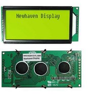
... User’s Guide NHD-0420H1Z-FL-GBW LCM (Liquid Crystal Display Module) RoHS Compliant NHD- Newhaven Display 0420- 4 Lines x 20 Characters H1Z- Version Line F- Transflective L- Yellow/Green LED B/L G- STN-Gray B- 6:00 View Wide Temperature (-20 ~ +70c) W- For product support, contact Newhaven Display International, LLC 2511 Technology Drive, #101 ...
Page 2
... Item Functions & Features Mechanical specifications Dimensional Outline Absolute maximum ratings Block diagram Pin description Contrast adjust Optical characteristics Electrical characteristics Timing Characteristics Instruction description Display character address code: character pattern Quality Specifications Newhaven Display DESCRIPTION CHANGED BY First issue Page 7-8 ...
Page 3
... O’clock ;Transflective †EL †Internal Power †CCFL ;External Power †Amber †Blue-Green †Wide ;Not Build-in ;Not Build-in ;Without †English-Eur †English-Russian open 79.0mm(L)*36.0mm(W)* Max13.0(H)mm 60.0mm(L)*28.0mm(W) 2.35mm(L)*5.15mm(W) 2.85mm(L)*6.15mm(W) Approx. Newhaven Display †STN-Blue †Transmissive ;5.0V input †3.3 input ;Yellow-Green †Super Wide †other ...
Page 4
...
Page 5
Item Power voltage Input voltage Operating temperature range Storage temperature range 5.Block diagram 6.Interface pin description Pin no. Symbol R 7~10 DB0~DB3 11~14 ...
Page 6
V : LCD Driving voltage V DD~ 0 VR: 10k~20k 8.Optical characteristics TN type display module (Ta=25 , VDD=5.0V) Item Symbol Viewing angle Contrast ratio Response time (rise) Response time (fall) STN type display module (Ta=25 , VDD=5.0V) ...
Page 7
Characteristics Write cycle (Ta=25 , VDD=5.0V) Parameter Symbol Enable cycle time Enable pulse width Enable rise/fall time t RS; R/W setup time t RS; R/W address hold t time Read data output delay t Read data hold time t ...
Page 8
Read cycle (Ta=25 , VDD=5.0V) Parameter Symbol Enable cycle time Enable pulse width Enable rise/fall time t RS; R/W setup time t RS; R/W address hold time Read data output delay Read data hold time t Read mode timing diagram ...
Page 9
To overcome the speed difference between the internal clock of SPLC780D and the MPU clock, SPLC780D performs internal operations by storing control in formations DR. The internal operation is determined according to the signal ...
Page 10
NOTE: When an MPU program with checking the busy flag (DB7) is made, it must be necessary 1/2fosc is necessary for executing the next instruction by the falling edge of the “E” signal after the busy flag (DB7) goes to ...
Page 11
This instruction is used to correct or search display data. During 2-line mode display, cursor moves to the 2nd line after the 40th digit of the 1st line. Note that display shift is performed simultaneously in all the lines. When ...
Page 12
D7 Write binary 8-bit data to DDRAM/CGRAM. The selection of RAM from DDRAM, and CGRAM, is set by the previous address set instruction (DDRAM address set, CGRAM address set). RAM set instruction can also determine the AC direction ...
Page 13
13.Standard character pattern ...
Page 14
SPECIFICATIONS 14.1 Standard of the product appearance test Manner of appearance test: The inspection should be performed in using 20W x 2 fluorescent lamps. Distance between LCM and fluorescent lamps should be 100 cm or more. Distance between LCM ...
Page 15
Specification of quality assurance AQL inspection standard Sampling method: MIL-STD-105E, Level II, single sampling Defect classification (Note not including) Classify Major Display state Non-display Minor Display state Polarizer Soldering Wire TAB Item Short or open circuit LC ...
Page 16
Note on defect classification No. Item 1 Short or open circuit LC leakage Flickering No display Wrong viewing direction Wrong Back-light 2 Contrast defect Background color deviation 3 Point defect, Black spot, dust (including Polarizer (X+Y)/2 Line defect, ...
Page 17
No Item 6 Chip Remark: X: Length direction Y: Short direction Z: Thickness direction t: Glass thickness W: Terminal Width Y W Criterion Acceptable criterion Acceptable criterion ...
Page 18
No. Item 7 Segment pattern W = Segment width I = (X+Y)/2 8 Back-light 9 Soldering 10 Wire 11* PCB Criterion (1) Pin hole I < 0.10mm is acceptable Point Size ...
Page 19
No Item 12 Protruded W: Terminal Width 13 TAB 14 Total no. of acceptable Defect Criterion Position TAB bonding strength test P (=F/TAB bonding width) 650gf/cm ,(speed rate: 1mm/min) 5pcs per SOA ...
Page 20
... Do not tamper in any way with the tabs on the metal frame not make any modification on the PCB without consulting Newhaven Display 5. When mounting a LCM, make sure that the PCB is not under any stress such as bending or twisting ...
Page 21
... Newhaven Display will not be responsible for any subsequent or consequential events or injury or damage to any personnel or user including third party personnel and/or user. Unless otherwise agreed in writing between Newhaven Display and the customer, Newhaven Display will only replace or repair any of its LCD which is found defective electrically or visually when inspected in accordance with Newhaven Display general LCD inspection standard ...