NHD-160128WG-BTMI-VZ#-1 Newhaven Display, NHD-160128WG-BTMI-VZ#-1 Datasheet
NHD-160128WG-BTMI-VZ#-1
Specifications of NHD-160128WG-BTMI-VZ#-1
NHD-160128WG-BTMI-VZ#
NHD-160128WG-BTMI-VZ#
Available stocks


Related parts for NHD-160128WG-BTMI-VZ#-1


NHD-160128WG-BTMI-VZ#-1 Summary of contents
Page 1
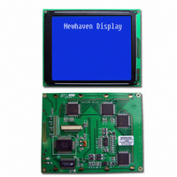
... User’s Guide NHD-160128WG-BTMI-VZ# LCM (Liquid Crystal Display Graphic Module) RoHS Compliant Newhaven Display NHD- 160 x 128 Dots 160128- WG- W- Version Line G- Display Type= Graphic B- Model/Serial Number White LED B/L T- STN-(negative)Blue M- Transflective, 6:00 View, Wide Temperature (-20 ~ +70c Build in Negative Voltage Z:ICNT7086 #: RoHS ...
Page 2
RECORDS OF REVISION VERSION DATE 0 2007.03.20 DOC. FIRST ISSUE REVISED PAGE NO. SUMMARY First issue ...
Page 3
Contents 1.Module Classification Information 2.Precautions in use of LCD Modules 3.General Specification 4.Absolute Maximum Ratings 5.Electrical Characteristics 6.Optical Characteristics 7.Power Supply for LCD Module and Contrast Adjust 8.Outline dimension and block diagram 9.Interface Pin Function 10.Display control instruction 11.Timing Characteristics ...
Page 4
... Classification Information NHD 160128 Brand Newhaven Display d Display Font 160 * 128 Dots e Factory Line Display Type H Character Type, G Graphic Type Model / Serial number: h Backlight Type N Without backlight B EL, Blue green D EL, Green W EL, White F CCFL, White Y LED, Yellow Green i LCD Mode ...
Page 5
LCD Modules (1) Avoid applying excessive shocks to the module or making any alterations or modifications to it. (2) Don’t make extra holes on the printed circuit board, modify its shape or change the components of ...
Page 6
Maximum Ratings ITEM Operating Temperature Storage Temperature Input Voltage Supply Voltage For Logic Supply Voltage For LCD 5.Electrical Characteristics ITEM Supply Voltage For Logic Supply Voltage For LCD Input High Volt. Input Low Volt. Output High Volt. Output Low ...
Page 7
Characteristics ITEM SYMBAL CONDITION (V) View Angle (H) Contrast Ratio CR T rise Response Time T fall 6.1 Definitions View Angles Z ( Visual angle direction ) T LCD Best visual angle direction ) Response Time ...
Page 8
Supply for LCD Module and Contrast Adjust Vcc Vadj LCD MODULE VSS Vee VDD-V0:LCD Operating Voltage Page ...
Page 9
DOT SIZE SCALE 10/1 WR T6963C RD MPU Controller CE C/D 80 series or HALT 68 series RESET DB0~DB7 Address Data 32K8 SRAM Vdd Bias and ...
Page 10
Pin Function Pin No. Symbol Level Vss 0V 3 VDD 5.0V Power supply for logic 4 Vadj 5 Vee WR=L , C/D=H ...
Page 11
The LCD Module has built in a T6963C LSI controller, It has an 8-bit parallel data bus and control lines for writing or reading through an MPU interface, it has a 128-word character generator ROM ( refer ...
Page 12
Flowchart of communications with MPU (1)Status Read A status check must be performed before data is read or written. Status check The Status of T6963C can be read from the data lines C/D H ...
Page 13
When using the MSB=0 command, a Status Read must be performed status check is not carried out, the T6963C cannot operate normally, even after a delay time. The hardware interrupt occurs during the address calculation ...
Page 14
When using the T6963C, first set the data, then set the command. Procedure for sending a command (a)The case of 1 date (Note) When sending more than two data, the last datum (or last two data)is valid. (b)The ...
Page 15
COMMAND DEFINITIONS COMMAND CODE 00100001 REGISTERS SETTING 00100010 00100100 01000000 01000001 SET CONTROL WORD 01000010 01000011 1000x000 1000x001 1000x011 MODE SET 1000x100 10000xxx 10001xxx 10010000 1001xx10 1001xx11 DISPLAY MODE 100101xx 100110xx 100111xx 10100000 10100001 10100010 CURSOR PATTERN 10100011 SELECT 10100100 ...
Page 16
BIT SET/RESET 1111x011 1111x100 1111x101 1111x110 1111x111 Setting registers CODE HEX. 00100001 21H SET CURSOR POINTER 00100010 22H SET OFFSET REGISTER 00100100 24H SET ADDRESS POINTER (1)Set Cursor Pointer The position of the cursor is ...
Page 17
T6963C assign External character generator, when character code set 80H TO FFH in using internal character generator. Character code 00H to 80H assign External character generator, when External generator mode. The senior five bits define the start address in external ...
Page 18
The relationship between display RAM data and display characters and are displayed by character generator RAM. (3)Set Address Pointer The Set Address Pointer command is used to indicate the start address for writing to (or reading from)external RAM. ...
Page 19
Page ...
Page 20
Set Control Word CODE HEX. 01000000 40H Set Text Home Address 01000001 41H Set Text Area 01000010 42H Set Graphic Home Address 01000011 43H Set Graphic Area The home address and column size are defined by this command. (1)Set Text ...
Page 21
Graphic Home Address The starting address of the external display RAM used for graphic display is defined by this command. The graphic home address indicates the leftmost and uppermost position. The relationship between external display RAM address and display ...
Page 22
Text Area The display columns are defined ...
Page 23
Graphic Area The display columns are defined by the hardware setting. This command can be used to adjust the columns of the graphic display. (Example) LCD size Graphic home address Graphic are Set 32 columns, 2 Lines 0000 0001 ...
Page 24
If the graphic area setting is set to match the desired number of columns on the LCD, the addressing scheme will be automatically modified so that the start address of each line equals the end address of the previous line ...
Page 25
The attribute operations are Reverse display, Character blink and Inhibit. The attribute data is written into the graphic area which was defined by the Set Control Word command. Only text display is possible in Attribute Function mode; graphic display is ...
Page 26
Cursor pattern select CODE FUNCTION 10100000 1-line cursor 10100001 2-line cursor 10100010 3-line cursor 10100011 4-line cursor 10100100 5-line ...
Page 27
B2H Auto Reset The command is convenient for sending a full screen of data from the external display RAM. After setting Auto mode, a Data Write (or Read) command is need not be sent between each datum. A Data ...
Page 28
Page ...
Page 29
Page ...
Page 30
Date Read/Write CODE HEX. 11000000 C0H Data Write and Increment ADP 11000001 C1H Data Read and Increment ADP 11000010 C2H Data Write and Decrement ADP 11000011 C3H Data Read and Decrement ADP 11000100 C4H Data Write and Non-variable ADP 11000101 ...
Page 31
Screen Peek CODE HEX. 11100000 E0H Screen Peek This command is used to transfer 1 byte of displayed data to the data stack; this byte can then be read from the MPU by data access. The logical combination of text ...
Page 32
Screen Copy CODE HEX. 11101000 E8H Screen Copy This command copies a single raster line of data to the graphic area. The start point must be set using the Set Address Pointer command. (Note 1) If the attribute function is ...
Page 33
Bit Set/Reset CODE FUNCTION 11110xxx Bit Reset 11111xxx Bit Set 1111x000 Bit 0 (LSB) 1111x001 Bit 1 1111x010 Bit 2 1111x011 Bit 3 1111x100 Bit 4 1111x101 Bit 5 1111x110 Bit 6 1111x111 Bit 7 (MSB) This command use to ...
Page 34
CHARACTER CODE MAP Page ...
Page 35
Page ...
Page 36
Characteristics Bus Timing ( Vss = VDD = Item C/D Set-up Time C/D Hold Time CE,RD,WR Pulse Width Data Set-up Time Data Hold Time Access Time Output Hold Time C/D CE RD,WR D0 ...
Page 37
Content of Reliability Test (wide temperature, -20 ~70 ) Test Item High Temperature Endurance test applying the high storage storage temperature for a long time. Low Temperature Endurance test applying the high storage storage temperature for a long time. ...
Page 38
Information Specification PARAMETER SYMBOL MIN Supply Current ILED Supply Voltage V Reverse Voltage VR Luminous IV Intensity Chromaticity X Coordinate Chromaticity Y Coordinate Life Time Color White Note: The LED of B/L is drive by current only, drive voltage ...
Page 39
Inspection specification NO Item 1.1 Missing vertical, horizontal segment, segment contrast defect. 1.2 Missing character , dot or icon. 1.3 Display malfunction. Electrical 1.4 No function or no display. 01 Testing 1.5 Current consumption exceeds product specifications. 1.6 LCD ...
Page 40
NO Item 05 Scratches Follow NO.3 LCD black spots, white spots, contamination Symbols Define: x: Chip length k: Seal width L: Electrode pad length: 6.1 General glass chip : 6.1.1 Chip on panel surface and crack between panels: Chipped 06 ...
Page 41
NO Item x: Chip length k: Seal width L: Electrode pad length 6.2 Protrusion over terminal : 6.2.1 Chip on electrode pad : Glass 06 crack Criterion y: Chip width z: Chip thickness t: Glass thickness a: LCD side length ...
Page 42
NO Item Cracked 07 glass Backlight 08 elements 09 Bezel The height of the COB should not exceed the height indicated in the assembly diagram. 10.4 There may not be more than 2mm of sealant outside the seal area on ...
Page 43
NO Item General 12 appearance Criterion Page 2.5 0.65 AQL 2.5 0.65 2.5 2.5 2.5 2.5 2.5 0.65 0.65 0.65 0.65 ...
Page 44
... Material List of Components for RoHs 1. Newhaven Display International hereby declares that all of or part of products (with the mark “#”in code), including, but not limited to, the LCM, accessories or packages, manufactured and/or delivered to your company (including your subsidiaries and affiliated company) directly or indirectly by our company (including our subsidiaries or affiliated companies) do not intentionally contain any of the substances listed in all applicable EU directives and regulations, including the following substances ...
Page 45
LCM Sample Estimate Feedback Sheet Newhaven Module Number 1 Panel Specification 1. Panel Type 2. View Direction 3. Numbers of Dots 4. View Area 5. Active Area 6. Operating Temperature 7. Storage Temperature 8. Others 2 Mechanical 1. PCB Size ...
Page 46
Brightness of B/L 5 B/L Solder Method 6 Others 7 Newhaven Module Number 5 Electronic Characteristics of Module 1. Input Voltage 2. Supply Current 3. Driving Voltage for LCD 4. Contrast for LCD 5. B/L Driving Method 6. Negative Voltage ...
Page 47
Sales signature Customer Signature Date Page ...