NHD-12864EZ-FL-YBW Newhaven Display, NHD-12864EZ-FL-YBW Datasheet - Page 13
NHD-12864EZ-FL-YBW
Manufacturer Part Number
NHD-12864EZ-FL-YBW
Description
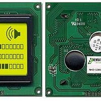
LCD MOD GRAPH 128X64 Y/G TRANSFL
Manufacturer
Newhaven Display
Specifications of NHD-12864EZ-FL-YBW
Display Type
LCD - Monochrome
Display Mode
Transflective
Viewing Area
72.00mm L x 40.00mm W
Backlight
LED - Yellow/Green
Dot Size
0.48mm W x 0.48mm H
Dot Pitch
0.52mm x 0.52mm
Dot Pixels
128 x 64
Interface
Serial
Pixel Density
128 x 64
Fluid Type
STN
Module Size (w X H X T)
93 mm x 70 mm x 13 mm
Viewing Area (w X H)
72 mm x 40 mm
Backlighting
LED
Background Color
Green, Yellow
Operating Temperature Range
- 20 C to + 70 C
Attached Touch Screen
No
Lead Free Status / RoHS Status
Lead free / RoHS Compliant
Lead Free Status / RoHS Status
Lead free / RoHS Compliant, Lead free / RoHS Compliant


NHD-12864EZ
The LCM enters serial mode when the J8 is set low. A two-line clock synchronous transfer
method is used. The LCM receives serial input data(SID) by synchronizing with a transfer
clock(SCLK) sent from the master side.
When the MPU interfaces with several LCD MODULES, chip select pin(CS) must be used. The transfer
clock(SCLK) input is activated by making chip select(CS) high. In addition, the transfer counter of the
LCM can be reset and serial transfer synchronized by making chip select(CS) low. Here, since the
data which was being sent at reset is cleared, restart the transfer from the first bit of this data. In a
minimum system where a single LCM interfaces to a single MPU, an interface can be constructed
from the transfer clock(SCLK) and serial input data(SID). In this case, chip select(CS) should be fixed
to high.
The transfer clock(SCLK) is independent of operational clock of the LCM. However, when several
instructions are continuously transferred, the instruction execution time determined by the operational
clock must be considered since the LCM does not have an internal transmit/receive buffer.
Following figure shows the basic procedure for transferring serial data. To begin with, transfer the start
byte. By receiving five consecutive bits of 1(synchronizing bit string) at the beginning of the start byte,
the transfer counter of the LCM is reset and serial transfer is synchronized. The 2 bits following the
synchronizing bit string(5 bits) specify transfer direction(RW bit) and register select(RS bit). Be sure to
transfer 0 in the 8 th bit.
After receiving the start synchronizing bit string, the RW bit(=0), and RS bit in the start byte, an 8-bit
instruction is received in 2 bytes: the higher 4 bits of the instruction are placed in the LSB of the first
byte, and the lower 4 bits of the instruction are placed in the LSB of the second byte. Be sure to transfer
0 in the following 4 bits of each byte.
Newhaven Display International, LLC
Page 13 of 22
Related parts for NHD-12864EZ-FL-YBW
Image
Part Number
Description
Manufacturer
Datasheet
Request
R

Part Number:
Description:
LCD COG GRAPH 128X64 WH TRANSFL
Manufacturer:
Newhaven Display

Part Number:
Description:
DISPLAY VFD ALPHA 1X20 6.5MM
Manufacturer:
Newhaven Display
Datasheet:

Part Number:
Description:
DISPLAY VFD ALPHA 1X16 5MM
Manufacturer:
Newhaven Display
Datasheet:

Part Number:
Description:
DISPLAY VFD 7-SEG 1X9 9.7MM
Manufacturer:
Newhaven Display
Datasheet:

Part Number:
Description:
DISPLAY VFD 7-SEG 1X6 20MM
Manufacturer:
Newhaven Display
Datasheet:

Part Number:
Description:
DISPLAY VFD 7-SEG 1X19 11MM
Manufacturer:
Newhaven Display
Datasheet:

Part Number:
Description:
DISPLAY VFD 7-SEG 1X3 8MM
Manufacturer:
Newhaven Display
Datasheet:

Part Number:
Description:
DISPLAY VFD CUSTOM DVD
Manufacturer:
Newhaven Display
Datasheet:

Part Number:
Description:
DISPLAY VFD CUST AUDIO
Manufacturer:
Newhaven Display
Datasheet:

Part Number:
Description:
DISPLAY VFD CUST AUDIO
Manufacturer:
Newhaven Display
Datasheet:

Part Number:
Description:
DISPLAY VFD 7-SEG 1X5 7.6MM
Manufacturer:
Newhaven Display
Datasheet:

Part Number:
Description:
DISPLAY VFD CUST APPLIANCE
Manufacturer:
Newhaven Display
Datasheet:

Part Number:
Description:
DISPLAY VFD CUSTOM DVD
Manufacturer:
Newhaven Display
Datasheet:

Part Number:
Description:
DISPLAY VFD 7-SEG 1X4 7.6MM
Manufacturer:
Newhaven Display
Datasheet:

Part Number:
Description:
DISPLAY VFD 7-SEG 1X9 8MM
Manufacturer:
Newhaven Display
Datasheet: