NHD-5.7-320240WFB-CTXI#-T-1 Newhaven Display, NHD-5.7-320240WFB-CTXI#-T-1 Datasheet - Page 7
NHD-5.7-320240WFB-CTXI#-T-1
Manufacturer Part Number
NHD-5.7-320240WFB-CTXI#-T-1
Description
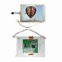
LCD DISP TFT 5.7" 320X240 WHI
Manufacturer
Newhaven Display
Datasheet
1.NHD-5.7-320240WFB-CTXI-T-1.pdf
(9 pages)
Specifications of NHD-5.7-320240WFB-CTXI#-T-1
Display Type
TFT - Color LCD
Display Mode
Transmissive
Viewing Area
118.28mm L x 88.60mm W
Backlight
LED - White
Dot Pixels
320 x 240 (QVGA)
Interface
Parallel
Pixel Density
320 x 240
Module Size (w X H X T)
149 mm x 109 mm x 11.5 mm
Backlighting
White LED
Lead Free Status / RoHS Status
Lead free / RoHS Compliant
Dot Size
-
Dot Pitch
-
Lead Free Status / Rohs Status
Details
Other names
NHD-5.7-320240WFB-CTXI#-T-1
NHD-5.7-320240WFB-CXTI#-T-1
NHD-5.7-320240WFB-CXTI#-T-1
NHD-5.7-320240WFB-CXTI#-T-1
NHD-5.7-320240WFB-CXTI#-T-1


Controller Information
Built‐in SSD1963 controller.
Please download specification at http://www.newhavendisplay.com/app_notes/SSD1963.pdf
8080 Mode Interface:
The 8080 mode MPU interface consists of CS#, D/C, RD#, WR#, and DB[7:0]. This interface uses WR# to define a write
cycle and RD# to define a read cycle. If the WR# goes LOW when the CS# signal is LOW, the data or command will be
latched into the system at the rising edge of WR#. Similarly, the read cycle will start when RD# goes LOW and end at the
rising edge of RD#. See the SSD1963 datasheet for detailed timing diagrams.
Command Instructions:
See the SSD1963 datasheet for the Instruction Table and Command Descriptions.
Pixel Data Format:
[7]
Related parts for NHD-5.7-320240WFB-CTXI#-T-1
Image
Part Number
Description
Manufacturer
Datasheet
Request
R

Part Number:
Description:
DISPLAY VFD ALPHA 1X20 6.5MM
Manufacturer:
Newhaven Display
Datasheet:

Part Number:
Description:
DISPLAY VFD ALPHA 1X16 5MM
Manufacturer:
Newhaven Display
Datasheet:

Part Number:
Description:
DISPLAY VFD 7-SEG 1X9 9.7MM
Manufacturer:
Newhaven Display
Datasheet:

Part Number:
Description:
DISPLAY VFD 7-SEG 1X6 20MM
Manufacturer:
Newhaven Display
Datasheet:

Part Number:
Description:
DISPLAY VFD 7-SEG 1X19 11MM
Manufacturer:
Newhaven Display
Datasheet:

Part Number:
Description:
DISPLAY VFD 7-SEG 1X3 8MM
Manufacturer:
Newhaven Display
Datasheet:

Part Number:
Description:
DISPLAY VFD CUSTOM DVD
Manufacturer:
Newhaven Display
Datasheet:

Part Number:
Description:
DISPLAY VFD CUST AUDIO
Manufacturer:
Newhaven Display
Datasheet:

Part Number:
Description:
DISPLAY VFD CUST AUDIO
Manufacturer:
Newhaven Display
Datasheet:

Part Number:
Description:
DISPLAY VFD 7-SEG 1X5 7.6MM
Manufacturer:
Newhaven Display
Datasheet:

Part Number:
Description:
DISPLAY VFD CUST APPLIANCE
Manufacturer:
Newhaven Display
Datasheet:

Part Number:
Description:
DISPLAY VFD CUSTOM DVD
Manufacturer:
Newhaven Display
Datasheet:

Part Number:
Description:
DISPLAY VFD 7-SEG 1X4 7.6MM
Manufacturer:
Newhaven Display
Datasheet:

Part Number:
Description:
DISPLAY VFD 7-SEG 1X9 8MM
Manufacturer:
Newhaven Display
Datasheet:

Part Number:
Description:
DISPLAY VFD 7-SEG 1X7 12.5MM
Manufacturer:
Newhaven Display
Datasheet: