HDSP-H211 Avago Technologies US Inc., HDSP-H211 Datasheet
HDSP-H211
Specifications of HDSP-H211
Available stocks


Related parts for HDSP-H211


HDSP-H211 Summary of contents
Page 1
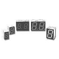
... HDSP-AX11/-AX13 Series, HDSP-FX11/-FX13 Series HDSP-GX11/-GX13 Series, HDSP-HX11/-HX13 Series HDSP-KX11/-KX13 Series Black Surface Seven Segment Displays Data Sheet Description These devices use industry standard size package and pinout. Available with black surface finish. All devices are available as either common anode or common cathode. ...
Page 2
Part Numbering System Notes: 1. For codes not listed in ...
Page 3
Package Dimensions (7.6 mm Series) Package Dimensions (10 mm Series: Single) 3 Internal Circuit Diagram Internal Circuit Diagram ...
Page 4
Package Dimensions (10 mm Series: Two Digit) 4 Internal Circuit Diagram ...
Page 5
Package Dimensions (14.2 mm Series: Single) Package Dimensions (14.2 mm Series: Two Digit) Diagram 5 Internal Circuit Diagram Internal Circuit Diagram ...
Page 6
... A Symbol Min. [1,2] I 315 V 330 400 PEAK O [3] d [4] V 3.0 R ΔV /° J-PIN Green HDSP-X51X Series 105 [3] 90 [4] 30 –40 to +100 Typ. Max. Units Test Conditions 600 μ 3600 650 3900 700 4200 ...
Page 7
... Reverse Voltage/Segment or DP Temperature Coefficient of V /Segment A413 Thermal Resistance LED Junction-to-Pin F413 H413 High Efficiency Red Device Series HDSP- Parameter A21X Luminous Intensity/Segment (Digit Average) F21X, G21X H21X, K21X All Forward Voltage/Segment or DP Devices Peak Wavelength Dominant Wavelength Reverse Voltage/Segment or DP ...
Page 8
... CIE chromaticity diagram and is that single wavelength which defines the color of the device Typical specification for reference only. Do not exceed absolute maximum ratings. 5. Green (HDSP-A51X/F51X/G51X/H512X/K51X) series displays are categorized for dominant wavelength. The category is designated by a number adjacent to the luminous intensity category letter. 8 Symbol Min ...
Page 9
AlGaAs Red Figure 1. Maximum allowable average or dc current vs. ambient temperature. Figure 3. Relative luminous intensity vs. dc forward current. 9 Figure 2. Forward current vs. forward voltage. Figure 4. Relative efficiency (luminous intensity ...
Page 10
HER, Green, Orange Figure 5. Maximum tolerable peak current vs. pulse duration – HER, Orange θ J-A = 770°C HER / ORANGE 25 GREEN ...
Page 11
... Orange HDSP-A41X Max. IV Bin Category 0.520 A 0.759 B 1.16 C 1.71 D 2.56 E 3.84 F 5. Max. K 0.650 L 0.923 M 1.39 N 2.08 3.14 HDSP-F41X/G41X IV Bin Category C Max. D 0.690 E 0.990 F 1.50 G 2.20 H 3.30 5.00 HDSP-H41X/K41X 7.50 IV Bin Category Min Max 0.284 0.433 0.354 0.541 0.443 0.677 ...
Page 12
... H 3.08 I 4.62 J 6.93 K 10.39 12 Intensity Bin Limits (mcd), continued Green HDSP-A5xx IV Bin Category Max. H 0.630 I 0.946 J 1.418 K 2.127 L 3.190 4.785 7.177 HDSP-F5xx/G5xx IV Bin Category H I Max. J 0.890 K 1.333 L 2.000 3.000 HDSP-H5xx/K5xx 4.500 IV Bin Category 6.751 Max. I 1.67 2.51 3.76 5.64 8.64 12 ...
Page 13
Color Categories Dominant Wavelength (nm) Color Bin Min. Green 2 573.00 3 570.00 4 567.00 5 564.00 Note: All categories are established for classification of products. Products may not be available in all categories. Please contact your Avago representa- tives ...