HDSP-F201 Avago Technologies US Inc., HDSP-F201 Datasheet - Page 9
HDSP-F201
Manufacturer Part Number
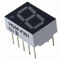
HDSP-F201
Description
LED 7-SEG 10MM CA HE RED RHD
Manufacturer
Avago Technologies US Inc.
Series
HDSP-F20xr
Specifications of HDSP-F201
Display Type
7-Segment
Common Pin
Common Anode
Number Of Digits/alpha
1
Size / Dimension
0.39" L x 0.50" W x 0.28" H (10mm x 13mm x 7mm)
Digit/alpha Size
0.40" (10.16mm)
Color
Red
Voltage - Forward (vf) Typ
2V
Current - Test
5mA
Millicandela Rating
1.2mcd
Wavelength - Peak
635nm
Power Dissipation (max)
105mW
Package / Case
10-DIP
Number Of Digits
1
Character Size
5.59 mm x 10.16 mm
Illumination Color
High Efficiency Red
Wavelength
626 nm
Operating Voltage
2 V
Operating Current
20 mA
Maximum Operating Temperature
+ 100 C
Minimum Operating Temperature
- 40 C
Luminous Intensity
1200 ucd
Power Consumption
105 mW
Viewing Area (w X H)
5.59 mm x 10.16 mm
Character Height
6.36 mm
Lead Free Status / RoHS Status
Lead free / RoHS Compliant
Lead Free Status / RoHS Status
Lead free / RoHS Compliant, Lead free / RoHS Compliant
Other names
516-1198-5
Available stocks
Company
Part Number
Manufacturer
Quantity
Price
Company:

Part Number:
HDSP-F201
Manufacturer:
Avago Technologies
Quantity:
135
Part Number:
HDSP-F201
Manufacturer:
AVAGO/安华高
Quantity:
20 000
Company:
Part Number:
HDSP-F201-DE000
Manufacturer:
MAXIM
Quantity:
101


Figure 9. Maximum Tolerable Peak
Current vs. Pulse Duration – Green.
Electrical/Optical
For more information on
electrical/optical characteristics,
please see Application Note 1005.
Contrast Enhancement
For information on contrast
enhancement please see
Application Note 1015.
Soldering/Cleaning
Cleaning agents from the ketone
family (acetone, methyl ethyl
ketone, etc.) and from the
chlorinated hydrocarbon family
Figure 11. Forward Current vs.
Forward Voltage.
90
80
70
60
50
40
30
20
10
0
1
HER SERIES,
ORANGE
GREEN SERIES
SERIES
V
F
– FORWARD VOLTAGE – V
2
3
YELLOW SERIES
4
5
(methylene chloride, trichloro–
ethylene, carbon tetrachloride,
etc.) are not recommended for
cleaning LED parts. All of these
various solvents attack or dissolve
the encapsulating epoxies used to
form the package of plastic LED
parts.
For information on soldering
LEDs please refer to Application
Note 1027.
Figure 12. Relative Luminous
Intensity vs. DC Forward Current.
4.0
3.5
3.0
2.5
2.0
1.5
1.0
0.5
0
0
I
5
F
– DC FORWARD CURRENT – mA
10
15
HER, YELLOW,
GREEN, ORANGE
Figure 10. Maximum Allowable DC Current vs.
Ambient Temperature.
20
25
50
45
40
35
30
25
20
15
10
5
0
20
30
30
T
GREEN
35
A
40
– AMBIENT TEMPERATURE – °C
40
50
60
9
Figure 13. Relative Efficiency
(Luminous Intensity per Unit
Current) vs. Peak Current.
HER, ORANGE
70
R
80
θ θ θ θ J-A
1.6
1.5
1.4
1.3
1.2
1.1
1.0
0.9
0.8
0.7
0.6
90
0
YELLOW
= 770°C/W
10
100
I
PEAK
YELLOW SERIES
20
110 120
– PEAK FORWARD CURRENT
PER SEGMENT – mA
30
40
50
HER SERIES,
ORANGE SERIES
GREEN SERIES
60
70
80
90
100
Related parts for HDSP-F201
Image
Part Number
Description
Manufacturer
Datasheet
Request
R

Part Number:
Description:
LED DISPLAY HEX 4X7 7.4MM HE RED
Manufacturer:
Avago Technologies US Inc.
Datasheet:

Part Number:
Description:
DISPLAY 4X7 NUM RDP BCD YLW
Manufacturer:
Avago Technologies US Inc.
Datasheet:
Part Number:
Description:
DISPLAY 4X7 HEX HI BRIGHT BCD YW
Manufacturer:
Avago Technologies US Inc.
Datasheet:

Part Number:
Description:
LED 7-SEG 7.6MM CC HE RED RHD
Manufacturer:
Avago Technologies US Inc.
Datasheet:

Part Number:
Description:
LED 7-SEG 7.6MM CA GREEN RHD
Manufacturer:
Avago Technologies US Inc.
Datasheet:

Part Number:
Description:
LED 7-SEG 7.6MM CC GREEN RHD
Manufacturer:
Avago Technologies US Inc.
Datasheet:

Part Number:
Description:
LED 7-SEG 7.6MM CA HE RED RHD
Manufacturer:
Avago Technologies US Inc.
Datasheet:
Part Number:
Description:
LED DISPLAY HEX 4X7 7.4MM GREEN
Manufacturer:
Avago Technologies US Inc.
Datasheet:
Part Number:
Description:
LED DISPLAY HEX 4X7 7.4MM HE RED
Manufacturer:
Avago Technologies US Inc.
Datasheet:

Part Number:
Description:
LED 7-SEG 14.2MM CC HE RED RHD
Manufacturer:
Avago Technologies US Inc.
Datasheet:

Part Number:
Description:
LED BAR GRAPH 10SEG GREEN
Manufacturer:
Avago Technologies US Inc.
Datasheet:

Part Number:
Description:
LED BAR GRAPH 10SEG YELLOW
Manufacturer:
Avago Technologies US Inc.
Datasheet:

Part Number:
Description:
LED 7-SEG 10MM CC GREEN RHD
Manufacturer:
Avago Technologies US Inc.
Datasheet:
Part Number:
Description:
DISPL 4X7 OVERRANGE +/- 1 BCD YW
Manufacturer:
Avago Technologies US Inc.
Datasheet:
Part Number:
Description:
DISPL 4X7 HEX OVERRANGE +/-1 BCD
Manufacturer:
Avago Technologies US Inc.
Datasheet: