HDSM-533B Avago Technologies US Inc., HDSM-533B Datasheet - Page 8
HDSM-533B
Manufacturer Part Number
HDSM-533B
Description
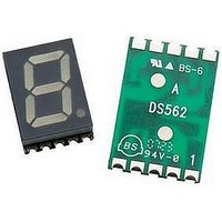
DISPLAY 1DIGIT BLU CC 0.56"
Manufacturer
Avago Technologies US Inc.
Type
Moduler
Specifications of HDSM-533B
Number Of Digits/alpha
1
Size / Dimension
0.75" L x 0.49" W x 0.15" H (19.00mm x 12.50mm x 3.75mm)
Digit/alpha Size
0.56" (14.22mm)
Display Type
7-Segment
Common Pin
Common Cathode
Color
Blue
Voltage - Forward (vf) Typ
3.3V
Current - Test
10mA
Millicandela Rating
13.5mcd
Wavelength - Peak
462nm
Power Dissipation (max)
100mW
Package / Case
10-SMD
No. Of Digits / Alpha
1
Character Size
14mm
Led Color
Blue
Common Connection
Common Cathode
Luminous Intensity
13.5mcd
Forward Current If
20mA
Forward Voltage
3.3V
Forward Voltage At If
3.3V
Number Of Digits
1
Package Type
SMD
Product Length (mm)
12.5mm
Product Height (mm)
3.75mm
Product Depth (mm)
19mm
Digit Size (in)
.56in
Character Displayed
Numeric
Viewing Area Length (mm)
8.1mm
Viewing Area Height (mm)
14.22mm
Emitting Color
Blue
Test Current (it)
10mA
Forward Current
25mA
Dominant Wave Length
470nm
Power Dissipation
100mW
Total Thickness
3.15mm
Reverse Voltage
5V
Mounting
Surface Mount
Operating Temperature Classification
Industrial
Pin Count
10
Configuration
Common Cathode
Number Of Elements
8
Peak Wavelength
462nm
Reverse Current
100uA
Lead Free Status / RoHS Status
Lead free / RoHS Compliant
Lead Free Status / RoHS Status
Lead free / RoHS Compliant, Lead free / RoHS Compliant


Intensity Bin Limits (mcd)
Green
Tolerance: ±15%
Note:
1. Bin categories are established for classification of products. Prod-
SMT Soldering Profile
Pb free reflow soldering Profile
Notes:
1. The peak temperature refers to the peak package body tempera-
2. Number of reflow process shall be limited to maximum 2 times only.
8
IV Bin Category
M
N
P
Q
ucts may not be available in all categories. Please contact your
Avago representative for information on currently available bins.
ture.
Cooling process to normal temperature is required between first
and second soldering process.
217°C
200°C
150°C
3°C/SEC. MAX.
3°C/SEC. MAX.
60 - 120 SEC.
Min.
5.401
8.601
21.801
13.701
245°C
TIME
(Acc. to J-STD-020C)
10 - 30 SEC.
100 SEC. MAX.
Max
8.600
13.700
21.800
34.700
6°C/SEC. MAX.
Yellow / Red / Orange
Tolerance: ±15%
Recommended soldering pattern (unit: mm)
IV Bin Category
N
P
Q
R
Recommended stencil window opening is 80%
1.8
3
2.45 x 4 = 9.8
Min.
8.601
13.701
21.801
34.701
16
Max
13.700
21.800
34.700
55.200
Related parts for HDSM-533B
Image
Part Number
Description
Manufacturer
Datasheet
Request
R

Part Number:
Description:
DISPLAY 1DIGIT YLW CA 0.28"
Manufacturer:
Avago Technologies US Inc.
Datasheet:
Part Number:
Description:
DISPLAY 1DIGIT ORN CA 0.28"
Manufacturer:
Avago Technologies US Inc.
Datasheet:

Part Number:
Description:
DISPLAY 1DIGIT RED CC 0.28"
Manufacturer:
Avago Technologies US Inc.
Datasheet:
Part Number:
Description:
DISPLAY 1DIGIT YLW CC 0.28"
Manufacturer:
Avago Technologies US Inc.
Datasheet:
Part Number:
Description:
DISPLAY 1DIGIT ORN CC 0.28"
Manufacturer:
Avago Technologies US Inc.
Datasheet:
Part Number:
Description:
DISPLAY 1DIGIT RED CA 0.39"
Manufacturer:
Avago Technologies US Inc.
Datasheet:
Part Number:
Description:
DISPLAY 1DIGIT YLW CA 0.39"
Manufacturer:
Avago Technologies US Inc.
Datasheet:
Part Number:
Description:
DISPLAY 1DIGIT ORN CA 0.39"
Manufacturer:
Avago Technologies US Inc.
Datasheet:
Part Number:
Description:
DISPLAY 1DIGIT RED CC 0.39"
Manufacturer:
Avago Technologies US Inc.
Datasheet:
Part Number:
Description:
DISPLAY 1DIGIT YLW CC 0.39"
Manufacturer:
Avago Technologies US Inc.
Datasheet:
Part Number:
Description:
DISPLAY 1DIGIT ORN CC 0.39"
Manufacturer:
Avago Technologies US Inc.
Datasheet:
Part Number:
Description:
DISPLAY 1DIGIT GRN CA 0.28"
Manufacturer:
Avago Technologies US Inc.
Datasheet:
Part Number:
Description:
DISPLAY 1DIGIT GRN CC 0.28"
Manufacturer:
Avago Technologies US Inc.
Datasheet:
Part Number:
Description:
DISPLAY 1DIGIT GRN CA 0.39"
Manufacturer:
Avago Technologies US Inc.
Datasheet:
Part Number:
Description:
DISPLAY 1DIGIT GRN CC 0.39"
Manufacturer:
Avago Technologies US Inc.
Datasheet: