HCMS-3914 Avago Technologies US Inc., HCMS-3914 Datasheet - Page 16
HCMS-3914
Manufacturer Part Number
HCMS-3914
Description
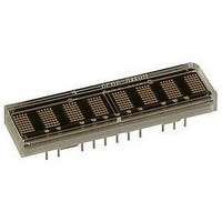
LED DISPLAY 5X7 8CHAR 3.8MM ORN
Manufacturer
Avago Technologies US Inc.
Series
HCMS-39xxr
Datasheet
1.HCMS-3902.pdf
(18 pages)
Specifications of HCMS-3914
Millicandela Rating
*
Internal Connection
*
Size / Dimension
*
Color
Orange
Configuration
*
Voltage - Forward (vf) Typ
*
Package / Case
26-DIP
Display Type
Alphanumeric
Number Of Digits/alpha
8
Digit/alpha Size
0.15" (3.8mm)
Character Format
Dot Matrix
Character Size
3.81mm
Led Color
Orange
Luminous Intensity
128µcd
No. Of Digits / Alpha
8
Display Area Width
35.56mm
Display Area Height
10.16mm
Emitting Color
Orange
Number Of Digits
8
Digit Size (in)
.15in
Viewing Area Height (mm)
3.71mm
Viewing Area Length (mm)
2.11mm
Package Type
DIP
Operating Supply Voltage (min)
3.1V
Operating Supply Voltage (typ)
3.3/5V
Operating Supply Voltage (max)
5.5V
Operating Temperature Classification
Industrial
Operating Temp Range
-40C to 85C
Mounting
Through Hole
Pin Count
14
Total Thickness (mm)
5.08mm
Opto Display Type
Panel
Pattern Type
Dot Matrix
Illumination Color
Orange
Wavelength
588 nm
Operating Voltage
5.5 V
Maximum Operating Temperature
+ 85 C
Minimum Operating Temperature
- 40 C
Lead Free Status / RoHS Status
Lead free / RoHS Compliant
Common Pin
-
Lead Free Status / Rohs Status
Compliant


Appendix A. Thermal Considerations
The display IC has a maximum junction temperature of
150°C. The IC junction temperature can be calculated
with Equation 1 in Table 3.
A typical value for Rθ
for a display mounted in a socket and covered with a
plastic filter. The socket is soldered to a .062 inch thick
PCB with .020-inch wide, one ounce copper traces. P
can be calculated as Equation 2 in Table 3.
Figure 9 shows how to derate the power of one IC
versus ambient temperature. Operation at high ambient
temperatures may require the power per IC to be
reduced. The power consumption can be reduced by
changing the N, I
has very little impact on the power consumption.
Figure 9. Maximum power dissipation per IC versus ambient temperature
16
1.3
1.2
1.1
1.0
0.9
0.8
0.7
0.6
0.5
0.4
0.3
0.2
0.1
0
25
30
T
35
A
– AMBIENT TEMPERATURE – °C
40
PIXEL
45
50
JA
, Osc cyc or V
55
is 100°C/W. This value is typical
R
60
θ J-A
65
= 100°C/W
70
75
LED
80
. Changing V
85
90
LOGIC
D
Related parts for HCMS-3914
Image
Part Number
Description
Manufacturer
Datasheet
Request
R

Part Number:
Description:
LED DISPLAY 5X7 4CHAR 5MM GREEN
Manufacturer:
Avago Technologies US Inc.
Datasheet:

Part Number:
Description:
LED DISPLAY 5X7 8CHAR 3.8MM YLW
Manufacturer:
Avago Technologies US Inc.
Datasheet:

Part Number:
Description:
LED DISPLAY 5X7 4CHAR 3.8MM YLW
Manufacturer:
Avago Technologies US Inc.
Datasheet:

Part Number:
Description:
LED DISPLAY 5X7 4CHAR 3.8MM ORN
Manufacturer:
Avago Technologies US Inc.
Datasheet:

Part Number:
Description:
LED DISPL 5X7 4CHAR 3.8MM ALGAAS
Manufacturer:
Avago Technologies US Inc.
Datasheet:
Part Number:
Description:
LED DISPLAY 5X7 4CHAR 3.8MM RED
Manufacturer:
Avago Technologies US Inc.
Datasheet:
Part Number:
Description:
LED DISPLAY 5X7 4CHAR 3.8MM ORN
Manufacturer:
Avago Technologies US Inc.
Datasheet:
Part Number:
Description:
LED DISPLAY 5X7 4CHAR 3.8MM YLW
Manufacturer:
Avago Technologies US Inc.
Datasheet:
Part Number:
Description:
LED DISPLAY 5X7 4CHAR 5MM YLW
Manufacturer:
Avago Technologies US Inc.
Datasheet:
Part Number:
Description:
LED DISPLAY 5X7 4CHAR 5MM ORN
Manufacturer:
Avago Technologies US Inc.
Datasheet:
Part Number:
Description:
LED DISPLAY 5X7 4CHAR 5MM GRN
Manufacturer:
Avago Technologies US Inc.
Datasheet:
Part Number:
Description:
LED DISPLAY 5X7 4CHAR 5MM RED
Manufacturer:
Avago Technologies US Inc.
Datasheet:
Part Number:
Description:
LED DISPLAY 5X7 4CHAR 3.8MM RED
Manufacturer:
Avago Technologies US Inc.
Datasheet:
Part Number:
Description:
LED DISPLAY 5X7 4CHAR 3.8MM GRN
Manufacturer:
Avago Technologies US Inc.
Datasheet:
Part Number:
Description:
LED DISPLAY 5X7 4CHAR 5MM GRN
Manufacturer:
Avago Technologies US Inc.
Datasheet: