HDSP-0881 Avago Technologies US Inc., HDSP-0881 Datasheet - Page 5
HDSP-0881
Manufacturer Part Number
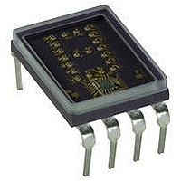
HDSP-0881
Description
DISPLAY 4X7 NUM RDP YELLOW
Manufacturer
Avago Technologies US Inc.
Series
HDSP-088xr
Datasheet
1.HDSP-0783.pdf
(8 pages)
Specifications of HDSP-0881
Millicandela Rating
*
Internal Connection
*
Size / Dimension
0.40" L x 0.53" W x 0.17" H (10.2mm x 13.5mm x 4.3mm)
Color
Yellow
Configuration
*
Voltage - Forward (vf) Typ
*
Package / Case
8-DIP
Display Type
Alphanumeric
Number Of Digits/alpha
1
Digit/alpha Size
0.29" (7.4mm)
Character Format
Dot Matrix
Character Size
7.4mm
Led Color
Yellow
Luminous Intensity
490µcd
No. Of Digits / Alpha
1
Display Area Width
10.2mm
Display Area Height
13.5mm
Number Of Digits
1
Illumination Color
Yellow
Wavelength
585 nm
Operating Voltage
4.5 V to 5.5 V
Maximum Operating Temperature
+ 100 C
Minimum Operating Temperature
- 55 C
Lead Free Status / RoHS Status
Lead free / RoHS Compliant
Common Pin
-
Lead Free Status / Rohs Status
Details


Electrical/Optical Characteristics
T
Description
Supply
Current
Power
Dissipation
Logic, Enable and Blanking Low-Level
Input Voltage
Logic, Enable High-Level Input Voltage
Blanking High-Voltage; Display Blanked
Logic and Enable Low-Level Input Current
Blanking Low-Level Input Current
Logic, Enable and Blanking High-Level
Input Current
Weight
Leak Rate
Notes:
4. The luminous intensity at a specific operating ambient temperature,
Operational Considerations
Electrical
These devices use a modified 4 x 7 dot matrix of light
emitting diodes to display decimal/hexadecimal numeric
information. The high efficiency red and yellow displays
use GaAsP/GaP LEDs and the high performance green
displays use GaP/GaP LEDs. The LEDs are driven by con-
stant current drivers, BCD information is accepted by
the display memory when the enable line is at logic low
and the data is latched when the enable is at logic high.
Using the enable pulse width and data setup and hold
times listed in the Recommended Operating Conditions
allows data to be clocked into an array of displays at a
6.7 MHz rate.
5
A
I
I
= –55°C to +100°C
v
v
Device
HDSP-078 Series
HDSP-079x Series
HDSP-088x Series –0.0112/°C
HDSP-098x Series –0.0104/°C
(T
(T
A
A
), may be approximated from the following exponential equation:
) = I
v
(25°C) e
HDSP-078x Series
HDSP-079x/-088x/-098x Series
HDSP-078x Series
HDSP-079x/-088x/-098x Series
[k(TA-25°C)]
–0.0131/°C
.
K
Symbol
I
P
V
V
V
I
I
I
CC
IL
BL
IH
T
IL
IH
BH
5. The dominant wavelength, l
6. The HDSP-088X and HDSP-098X series devices are categorized as to
7. All typical values at V
Test Conditions
V
Characters “5.” or
“B” displayed
V
Characters “5.” or
“B” displayed
V
V
V
V
V
The decimal point input is active low true and this data
is latched into the display memory in the same fashion
as the BCD data. The decimal point LED is driven by the
on-board IC.
The blanking control input on the hexadecimal displays
blanks (turns off ) the displayed information without dis-
turbing the contents of display memory. The display is
blanked at a minimum threshold level of 2.0 volts. When
blanked, the display standby power is nominally 250 mW
at T
The ESD susceptibility of the IC devices is Class A of MIL-
STD-883 or Class 2 of DOD-STD-1686 and DOD-HDBK-
263.
CC
CC
CC
CC
IL
CC
IH
gram and represents the single wavelength which defines the color of
the device.
dominant wavelength with the category designated by a number on the
back of the display package.
= 0.4 V
= 2.4 V
= 5.5 V
= 5.5 V
= 4.5 V
= 5.5 V
= 5.5 V
A
= 25°C.
CC
= 5.0 V and T
Min.
2.0
2.3
d
, is derived from the CIE chromaticity dia-
Typ.
78
120
390
690
1.0
A
= 25°C.
[7]
105
175
573
963
0.8
–1.6
–10
+40
5 x 10
Max.
-8
mA
mW
V
V
V
mA
µA
µA
gm
cc/sec
Unit
Related parts for HDSP-0881
Image
Part Number
Description
Manufacturer
Datasheet
Request
R

Part Number:
Description:
LED DISPLAY HEX 4X7 7.4MM HE RED
Manufacturer:
Avago Technologies US Inc.
Datasheet:

Part Number:
Description:
DISPLAY 4X7 NUM RDP BCD YLW
Manufacturer:
Avago Technologies US Inc.
Datasheet:
Part Number:
Description:
DISPLAY 4X7 HEX HI BRIGHT BCD YW
Manufacturer:
Avago Technologies US Inc.
Datasheet:

Part Number:
Description:
LED 7-SEG 7.6MM CC HE RED RHD
Manufacturer:
Avago Technologies US Inc.
Datasheet:

Part Number:
Description:
LED 7-SEG 7.6MM CA GREEN RHD
Manufacturer:
Avago Technologies US Inc.
Datasheet:

Part Number:
Description:
LED 7-SEG 7.6MM CC GREEN RHD
Manufacturer:
Avago Technologies US Inc.
Datasheet:

Part Number:
Description:
LED 7-SEG 7.6MM CA HE RED RHD
Manufacturer:
Avago Technologies US Inc.
Datasheet:
Part Number:
Description:
LED DISPLAY HEX 4X7 7.4MM GREEN
Manufacturer:
Avago Technologies US Inc.
Datasheet:
Part Number:
Description:
LED DISPLAY HEX 4X7 7.4MM HE RED
Manufacturer:
Avago Technologies US Inc.
Datasheet:

Part Number:
Description:
LED 7-SEG 14.2MM CC HE RED RHD
Manufacturer:
Avago Technologies US Inc.
Datasheet:

Part Number:
Description:
LED BAR GRAPH 10SEG GREEN
Manufacturer:
Avago Technologies US Inc.
Datasheet:

Part Number:
Description:
LED BAR GRAPH 10SEG YELLOW
Manufacturer:
Avago Technologies US Inc.
Datasheet:

Part Number:
Description:
LED 7-SEG 10MM CC GREEN RHD
Manufacturer:
Avago Technologies US Inc.
Datasheet:
Part Number:
Description:
DISPL 4X7 OVERRANGE +/- 1 BCD YW
Manufacturer:
Avago Technologies US Inc.
Datasheet:
Part Number:
Description:
DISPL 4X7 HEX OVERRANGE +/-1 BCD
Manufacturer:
Avago Technologies US Inc.
Datasheet: