HDSP-5707 Avago Technologies US Inc., HDSP-5707 Datasheet - Page 8
HDSP-5707
Manufacturer Part Number
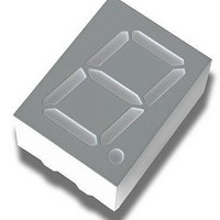
HDSP-5707
Description
DISPLAY 7SEGMENT YELLOW CA 0.56"
Manufacturer
Avago Technologies US Inc.
Type
Moduler
Datasheet
1.HDSP-5503-GH000.pdf
(10 pages)
Specifications of HDSP-5707
Display Type
7-Segment
Common Pin
Common Anode
Number Of Digits/alpha
1
Size / Dimension
0.67" L x 0.49" W x 0.31" H (17.02mm x 12.57mm x 8.00mm)
Digit/alpha Size
0.56" (14.22mm)
Color
Yellow
Voltage - Forward (vf) Typ
2.1V
Current - Test
10mA
Millicandela Rating
1.8mcd
Wavelength - Peak
583nm
Power Dissipation (max)
80mW
Package / Case
10-DIP (0.600", 15.24mm), 9 Leads
Number Of Digits
1
Character Size
14.2 mm
Illumination Color
Yellow
Wavelength
645 nm
Operating Voltage
2.1 V
Operating Current
60 mA
Maximum Operating Temperature
+ 100 C
Minimum Operating Temperature
- 40 C
Luminous Intensity
1800 ucd
Package Type
DIP
Product Length (mm)
17.1mm
Product Height (mm)
8mm
Product Depth (mm)
12.4mm
Digit Size (in)
.56in
Character Displayed
Numeric
Emitting Color
Yellow
Forward Voltage
2.5V
Test Current (it)
10mA
Forward Current
20mA
Dominant Wave Length
586nm
Power Dissipation
80mW
Total Thickness
8mm
Reverse Voltage
40V
Mounting
Through Hole
Operating Temperature Classification
Industrial
Pin Count
10
Configuration
Common Anode
Number Of Elements
6
Peak Wavelength
583nm
Lead Free Status / RoHS Status
Lead free / RoHS Compliant
Lead Free Status / RoHS Status
Lead free / RoHS Compliant, Lead free / RoHS Compliant


Figure 3. Maximum Allowable DC Current vs. Ambient Temperature.
Figure 5. Relative Luminous Intensity vs. DC Forward Current.
8
AlGaAs Red
Figure 1. Maximum Tolerable Peak Current vs. Pulse
Duration – Red.
50
45
40
35
30
25
20
15
10
5
0
2.00
1.75
1.50
1.25
1.00
0.75
0.50
0.25
20
AlGaAs RED
0
I
0
F
30
– FORWARD CURRENT PER SEGMENT – mA
T
A
40
– AMBIENT TEMPERATURE – C
5
50
10
60
15
70
AlGaAs RED
20
80
Rθ
25
J-A
90
= 770 C/W
100 110
30
35
120
40
Figure 4. Forward Current vs. Forward Voltage.
Figure 6. Relative Efficiency (Luminous Intensity per
Unit Current) vs. Peak Current.
160
140
120
100
80
60
40
20
1.4
1.2
1.0
0.8
0.6
Figure 2. Maximum Tolerable Peak Current vs. Pulse
Duration – AlGaAs Red.
0
0
0.5
0.5
I
PEAK
V
AlGaAs RED
F
1.0
– FORWARD VOLTAGE – V
– PEAK FORWARD CURRENT
PER SEGMENT – mA
5.0
1.5
2.0
AlGaAs RED
2.5
50.0
3.0
150.0
3.5
4.0
Related parts for HDSP-5707
Image
Part Number
Description
Manufacturer
Datasheet
Request
R

Part Number:
Description:
LED 7-SEG 7.6MM CC HE RED RHD
Manufacturer:
Avago Technologies US Inc.
Datasheet:

Part Number:
Description:
LED 7-SEG 7.6MM CA HE RED RHD
Manufacturer:
Avago Technologies US Inc.
Datasheet:

Part Number:
Description:
LED 7-SEG 7.6MM CA GREEN RHD
Manufacturer:
Avago Technologies US Inc.
Datasheet:

Part Number:
Description:
LED 7-SEG 7.6MM CC GREEN RHD
Manufacturer:
Avago Technologies US Inc.
Datasheet:

Part Number:
Description:
LED DISPLAY HEX 4X7 7.4MM HE RED
Manufacturer:
Avago Technologies US Inc.
Datasheet:

Part Number:
Description:
LED 7-SEG 14.2MM CC HE RED RHD
Manufacturer:
Avago Technologies US Inc.
Datasheet:

Part Number:
Description:
LED BAR GRAPH 10SEG GREEN
Manufacturer:
Avago Technologies US Inc.
Datasheet:

Part Number:
Description:
LED BAR GRAPH 10SEG YELLOW
Manufacturer:
Avago Technologies US Inc.
Datasheet:

Part Number:
Description:
LED DISPLAY 5X7 8CHAR 5MM HE RED
Manufacturer:
Avago Technologies US Inc.
Datasheet:

Part Number:
Description:
LED 7-SEG 14.2MM 2DIG CC HER RHD
Manufacturer:
Avago Technologies US Inc.
Datasheet:

Part Number:
Description:
LED DISPLAY 5X7 8CHAR 5MM GREEN
Manufacturer:
Avago Technologies US Inc.
Datasheet:
Part Number:
Description:
LED DISPLAY 5X7 8CHAR 5MM GREEN
Manufacturer:
Avago Technologies US Inc.
Datasheet:
Part Number:
Description:
LED DISPLAY 5X7 8CHAR 5MM YLW
Manufacturer:
Avago Technologies US Inc.
Datasheet:
Part Number:
Description:
LED DISPLAY 5X7 8CHAR 5MM RED
Manufacturer:
Avago Technologies US Inc.
Datasheet:

Part Number:
Description:
LED DISPLAY 5X7 8CHAR 7MM HE RED
Manufacturer:
Avago Technologies US Inc.
Datasheet: