PD4437 OSRAM Opto Semiconductors Inc, PD4437 Datasheet
PD4437
Specifications of PD4437
PD4437
Q68000A8369


Related parts for PD4437


PD4437 Summary of contents
Page 1
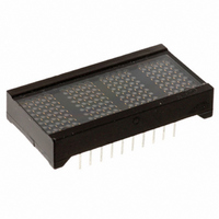
Dot Matrix Alphanumeric Programmable Display Lead (Pb) Free Product - RoHS Compliant PD243X, PD353X, PD443X PD243X DESCRIPTION These Programmable Displays are four digit display sys- tem modules. The characters are 5. 3.56 mm (0.20" ...
Page 2
... Ordering Information Type PD2435 PD2436 PD2437 PD3535 PD3536 PD3537 PD4435 PD4436 PD4437 2006-01-23 PD243X, PD353X, PD443X Color of Emission Character Height mm (inch) high efficiency red red bright green high efficiency red red bright green high efficiency red red bright green 2 Ordering Code Q68000A3561 5 ...
Page 3
Maximum Ratings Parameter Operating temperature range Storage temperature range Viewing angle (off normal axis DC Supply Voltage Input Voltage Relative to GND (all inputs) Solder temperature 1.59 mm (0.063“) below seating plane, t < 5.0 s Characteristics ...
Page 4
PD243X 6.35 (0.250) 3.18 (0.125) Pin 1 Location PD353X 0.46 (0.018) x 0.31 (0.012) typ. 6.35 (0.250) 4.45 (0.175) 2006-01-23 Pin 1 Indicator EIA Date Code Luminous PD243X Z Intensity OSRAM YYWW V Code 2.54 (0.100) typ. 0.46 (0.018) x ...
Page 5
PD443X 7.62 (0.300) 1.27 (0.050) Top View 2006-01-23 Dimensions in mm (inch) Pin 1 Indicator EIA Date Code Part No. Luminous Intensity Code PD443X Z OSRAM YYWW V 2.54 (0.100) typ. 0.46 (0.018) x 0.31 (0.012) typ. ±0.05 (0.002) 38.1 ...
Page 6
Timing Characteristics—Data “Write” Cycle CE0, CE1 T CES A0 D0– ACC Notes: 1. Wait 1.0 µs between any Reads or Writes after writing a Control Word with a Clear (D7=1). ...
Page 7
DC Characteristics at 25°C Parameter (Blank LEDs/unit (100% Bright) CC PD243X PD353X PD443X (1) I (except Data I/O ...
Page 8
Functional Description The block diagram includes 5 major blocks and internal registers (indicated by dotted lines). Display Memory consists bit RAM block. Each of the four 8-bit words holds 7-bits of ASCII data (bits D0–D6) ...
Page 9
There are five registers within the display. Four of these registers are used to hold the ASCII/attribute code of the four display char- acters. The fifth register is the Control Word, which is used to blink, blank, clear, or dim ...
Page 10
*“Cursor”= all dots in ...
Page 11
How to Load Information Into the Display Information loaded into the display can be either ASCII data or Control Word data. The following procedure (see also Typical Loading Sequence) will demonstrate a typical loading sequence and the resulting visual display. ...
Page 12
Electrical and Mechanical Considerations The CMOS IC of the display is designed to provide resistance to both Electrostatic Discharge Damage and Latch Up due to voltage or current surges. Several precautions are strongly recommended to avoid overstressing these built-in safeguards. ...
Page 13
Revision History: 2006-01-23 Previous Version: 2004-12-09 Page Subjects (major changes since last revision) all Lead free device Attention please! The information describes the type of component and shall not be considered as assured characteristics. Terms of delivery and rights to ...
Page 14
Post Solder Cleaning Procedures The least offensive cleaning solution is hot D.l. water (60 °C) for less than 15 minutes. Addition of mild saponifiers is acceptable. Do not use commercial dishwasher detergents. For faster cleaning, solvents may be used. Carefully ...