IPD2547A OSRAM Opto Semiconductors Inc, IPD2547A Datasheet - Page 8
IPD2547A
Manufacturer Part Number
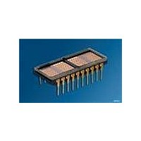
IPD2547A
Description
DISPLAY 4CHAR .250" GREEN
Manufacturer
OSRAM Opto Semiconductors Inc
Series
Alphanumeric Programmable Display™r
Datasheet
1.IPD2545A.pdf
(12 pages)
Specifications of IPD2547A
Millicandela Rating
150µcd
Size / Dimension
1.20" L x 0.49" W x 0.17" H (30.48mm x 12.45mm x 4.32mm)
Color
Green
Configuration
5 x 7
Number Of Digits
4
Character Size
0.252 in
Illumination Color
Green
Wavelength
568 nm
Maximum Operating Temperature
+ 100 C
Minimum Operating Temperature
- 55 C
Luminous Intensity
150 ucd
Viewing Area (w X H)
4.32 mm x 6.4 mm
Display Type
5 x 7 Dot Matrix
Lead Free Status / RoHS Status
Lead free / RoHS Compliant
Voltage - Forward (vf) Typ
-
Internal Connection
-
Lead Free Status / Rohs Status
Details
Other names
Q68000A9884


Programming the IPD2545/7/8A
There are five registers within the IPD2545/7/8A display. Four of
these registers are used to hold the ASCII/attribute code of the
four display characters. The fifth register is the Control Word,
which is used to blink, blank, clear, or dim the entire display, or to
change the presentation (attributes) of individual characters.
Addressing
The addresses within the display device are shown below. Digit 0
is the rightmost digit of the display, while Digit 3 is on the left.
Although there is only one Control Word, it is duplicated at the four
address locations 0-3. Data can be read from any of these loca-
tions. When one of these locations is written to, all of them will
change together.
Bit D7 of any of the display digit locations is used to allow an
attribute to be assigned to that digit. The attributes are discussed
in the next section. If Bit D7 is set to a one, that character will be
displayed using the attribute. If bit D7 is cleared, the character will
display normally.
Control Word Format
2006-03-03
A2
0
1
1
1
1
A1
X
0
0
1
1
Address
D7
0
1
Clear
A0
X
0
1
0
1
Clear
Standard operation
Clear entire display
D7
D6
0
1
Lamp
Lamp Test
Standard operation
Display all dots at 50% brightness
Test
D6
Contents
Control Word
Digit 0 (rightmost)
Digit 1
Digit 2
Digit 3 (leftmost)
D5
0
1
Blink
Blink
Blink attribute disabled
Blink entire display
D5
D4
0
1
Attribute
Attribute Enable
Disable above attributes
Enable above attributes
Enable
D4
D3
0
0
1
1
8
D2
0
1
0
1
Control Word
When address bit A2 is taken low, the Control Word is accessed.
The same Control Word appears in all four of the lower address
spaces of the display. Through the Control Word, the display can
be cleared, the lamps can be tested, display brightness can be
selected, and attributes can be set for any characters which have
been loaded with their most significant bit (D7) set high.
Brightness (D0, D1): The state of the lower two bits of the Control
Word are used to set the brightness of the entire display, from 0%
to 100%. The table below shows the correspondence of these bits
to the brightness.
Attributes (D2–D4): Bits D2, D3, and D4 control the visual
attributes (i.e., blinking, alternate) of those display digits which
have been written with bit D7 set high. In order to use any of the
four attributes, the Cursor Enable bit (D4 in the Control Word) must
be set. When the Cursor Enable bit is set, and bit D7 in a character
location is set, the character will take on one of the following dis-
play attributes.
D3
D7
0
0
0
0
X=don’t care
Attributes
Attributes
Display cursor instead
of character
Blink character
Display blinking cursor
instead of character
Alternate character
with cursor
D6
0
0
0
0
IPD2545A, IPD2547A, IPD2548A
D2
D5
X
X
X
X
D4
X
X
X
X
D1
Brightness
D1 D0 Brightness
0
0
1
1
D3
X
X
X
X
0
1
0
1
0% (blank)
25%
50%
100%
D0
D2
X
X
X
X
IDCW5163
D1
0
0
1
1
D0
0
1
0
1
Operation
Blank
25% brightness
50% brightness
Full brightness
Related parts for IPD2547A
Image
Part Number
Description
Manufacturer
Datasheet
Request
R

Part Number:
Description:
INTELLIGENT DISP 4CHAR 5X7 HERED
Manufacturer:
OSRAM Opto Semiconductors Inc
Datasheet:

Part Number:
Description:
DISPLAY 8DIGIT CERAMIC GREEN
Manufacturer:
OSRAM Opto Semiconductors Inc
Datasheet:

Part Number:
Description:
EMITTER IR 950NM 5MM SMD RADIAL
Manufacturer:
OSRAM Opto Semiconductors Inc
Datasheet:

Part Number:
Description:
LED TOPLED GREEN 570NM 2-PLCC
Manufacturer:
OSRAM Opto Semiconductors Inc
Datasheet:

Part Number:
Description:
INTERRUPTER RELFECT W/FILTR SMD
Manufacturer:
OSRAM Opto Semiconductors Inc
Datasheet:

Part Number:
Description:
LED Displays 5x7 Green 0.145 , 4-CHARACTER
Manufacturer:
OSRAM Opto Semiconductors Inc
Datasheet:

Part Number:
Description:
Q65110A4321_SIDELED PURE GREEN EOL150407
Manufacturer:
OSRAM Opto Semiconductors Inc
Datasheet:
Part Number:
Description:
Q65110A1202_RO DETECTOR 3/5MM_TR_RO
Manufacturer:
OSRAM Opto Semiconductors Inc
Datasheet:

Part Number:
Description:
PHOTODIODE 900NM 3MM W/FILTER
Manufacturer:
OSRAM Opto Semiconductors Inc
Datasheet:
Part Number:
Description:
INTELLIGENT DISP 4CHAR 5X7 HERED
Manufacturer:
OSRAM Opto Semiconductors Inc
Datasheet:
Part Number:
Description:
LED TOPLED GREEN 570NM 2-PLCC
Manufacturer:
OSRAM Opto Semiconductors Inc
Datasheet:
Part Number:
Description:
PHOTODIODE 900NM 3MM W/FILTER
Manufacturer:
OSRAM Opto Semiconductors Inc
Datasheet:

Part Number:
Description:
PHOTODIODE 850NM THRU-HOLE
Manufacturer:
OSRAM Opto Semiconductors Inc
Datasheet:

Part Number:
Description:
PHOTODIODE 880NM W/FILTER SMD
Manufacturer:
OSRAM Opto Semiconductors Inc
Datasheet: