M0240SD-402MDAR1-3 Newhaven Display, M0240SD-402MDAR1-3 Datasheet - Page 17
M0240SD-402MDAR1-3
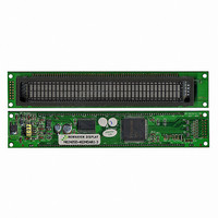
Manufacturer Part Number
M0240SD-402MDAR1-3
Description
MODULE VF CHAR 2X40 5.34MM
Manufacturer
Newhaven Display
Datasheet
1.M0240SD-402MDAR1-3.pdf
(21 pages)
Specifications of M0240SD-402MDAR1-3
Outline L X W X H
182.00mm x 33.50mm x 17.60mm
Viewing Area
134.75mm L x 11.50mm W
Display Format
40 x 2
Display Type
Character
Format
5 x 8 Dots
Voltage - Supply
4.5 V ~ 5.5 V
Character Size
5.34mm H x 2.10mm W
Interface
Parallel
Operating Temperature
-20°C ~ 70°C
Product
Character Display Modules
Character Count X Line
40 x 2
Module Size (w X H X T)
182 mm x 33.5 mm x 17.6 mm
Voltage Rating
4.5 V to 5.5 V
Operating Temperature Range
- 20 C to + 70 C
Dot Format
5 x 8
Viewing Area (w X H)
134.75 mm x 11.5 mm
Lead Free Status / RoHS Status
Lead free / RoHS Compliant
Number Of Dots
-
Lead Free Status / Rohs Status
Details


STANDARD
NAME
6.2.2 Cursor Home
6.2.3 Entry Mode Set
This instruction
(1) Clears the contents of the address counter (ACC) to 00H.
(2) Sets the address counter (ACC) to point to the DD-RAM.
(3) Sets the display for zero character shift (returns original position).
(4) If the cursor is displayed, moves the left most character in the top line (upper line).
I/D=1: The address counter (ACC) is incremented.
I/D=0: The address counter (ACC) is decremented.
The S bit enable display shift, instead of cursor shift , after each write or read to the DD-RAM.
The direction in which the display is shifted is opposite in sense to that of the cursor.
For example, if S=0 and I/D=1, the cursor would shift one character to the right after a MPU writes to
DD-RAM. However if S=1 and I/D=1, the display would shift one character to the left and the cursor would
maintain its position on panel.
The cursor will already be shifted in the direction selected by I/D during reads of the DD-RAM,
irrespective of the value of S. Similarly reading and writing the CG-RAM always shift the cursor.
Also both lines are shifted simultaneously.
The I/D bit selects the way in which the contents of the address counter (ACC) are modified after every
access to DD-RAM or CG-RAM.
Table-14 Cursor move and Display shift by the “Entry Mode Set”
I/D
S=1: Display shift enabled.
S=0: Cursor shift enabled.
0
1
0
1
DB7 DB6 DB5 DB4 DB3 DB2 DB1 DB0
DB7 DB6 DB5 DB4
0
0
S
0
0
1
1
RS=0, R/W=0
RS=0, R/W=0
0
0
The cursor moves one character to the
left.
The cursor moves one character to the
right.
The display shifts one character to the
right without cursor’s move.
The display shifts one character to the left
without cursor’s move.
0
0
After writing DD-RAM data
0
0
0
DB3 DB2 DB1 DB0
0
0
1
1
I/D
The cursor moves one character
to the left.
The cursor moves one character to
the right.
The cursor moves one character to
the left.
The cursor moves one character
to the right.
02H to 03H
After reading DD-RAM data
DOCUMENT NO.
04H to 07H
REV.NO
00
16/20
PAGE
Related parts for M0240SD-402MDAR1-3
Image
Part Number
Description
Manufacturer
Datasheet
Request
R

Part Number:
Description:
DISPLAY VFD ALPHA 1X20 6.5MM
Manufacturer:
Newhaven Display
Datasheet:

Part Number:
Description:
DISPLAY VFD ALPHA 1X16 5MM
Manufacturer:
Newhaven Display
Datasheet:

Part Number:
Description:
DISPLAY VFD 7-SEG 1X9 9.7MM
Manufacturer:
Newhaven Display
Datasheet:

Part Number:
Description:
DISPLAY VFD 7-SEG 1X6 20MM
Manufacturer:
Newhaven Display
Datasheet:

Part Number:
Description:
DISPLAY VFD 7-SEG 1X19 11MM
Manufacturer:
Newhaven Display
Datasheet:

Part Number:
Description:
DISPLAY VFD 7-SEG 1X3 8MM
Manufacturer:
Newhaven Display
Datasheet:

Part Number:
Description:
DISPLAY VFD CUSTOM DVD
Manufacturer:
Newhaven Display
Datasheet:

Part Number:
Description:
DISPLAY VFD CUST AUDIO
Manufacturer:
Newhaven Display
Datasheet:

Part Number:
Description:
DISPLAY VFD CUST AUDIO
Manufacturer:
Newhaven Display
Datasheet:

Part Number:
Description:
DISPLAY VFD 7-SEG 1X5 7.6MM
Manufacturer:
Newhaven Display
Datasheet:

Part Number:
Description:
DISPLAY VFD CUST APPLIANCE
Manufacturer:
Newhaven Display
Datasheet:

Part Number:
Description:
DISPLAY VFD CUSTOM DVD
Manufacturer:
Newhaven Display
Datasheet:

Part Number:
Description:
DISPLAY VFD 7-SEG 1X4 7.6MM
Manufacturer:
Newhaven Display
Datasheet:

Part Number:
Description:
DISPLAY VFD 7-SEG 1X9 8MM
Manufacturer:
Newhaven Display
Datasheet:

Part Number:
Description:
DISPLAY VFD 7-SEG 1X7 12.5MM
Manufacturer:
Newhaven Display
Datasheet: