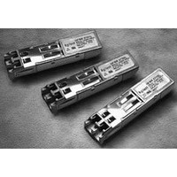
HFBR-57E0PZ Avago Technologies US Inc., HFBR-57E0PZ Datasheet

HFBR-57E0PZ
Specifications of HFBR-57E0PZ
Available stocks
Related parts for HFBR-57E0PZ
HFBR-57E0PZ Summary of contents
Page 1
... IC which converts differential PECL logic signals, ECL referenced (shifted +3.3 V supply, into an analog LED drive current. Receiver Section The receiver section of the HFBR-57E0 utilizes an InGaAs PIN photodiode coupled to a custom silicon transimped- ance preamplifier IC packaged in the optical subas- sembly portion of the receiver. ...
Page 2
... HFBR-57E0. The connection diagram of the module is shown in Figure 2. Figures 5 and 7 depict the external configuration and dimensions of the module. Installation The HFBR-57E0 can be installed in or removed from any MultiSource Agreement (MSA) – compliant Small Form Pluggable port regardless of whether the host equip- OPTICAL INTERFACE ...
Page 3
... MSA that defines the serial identification protocol. This protocol uses the 2-wire serial CMOS E2PROM protocol of the ATMEL AT24C01A or equivalent. The contents of the HFBR-57E0 serial ID memory are defined in Table 3 as specified in the SFP MSA. Functional Data I/O The HFBR-57E0 fiberoptic transceiver is designed to ac- cept industry standard differential signals ...
Page 4
... Contact your Avago sales representative for additional details. 4 Ordering Information The HFBR-57E0 1300 nm product is available for produc- tion orders through the Avago Component Field Sales Offices and Authorized Distributors worldwide. For technical information regarding this product, please visit the Avago website at www.avagotech.com. ...
Page 5
... SO+ 50 Ω SO– 4 SerDes 10 μF 50 Ω SI+ 50 Ω SI– μH 1 μH 3.3 V 0.1 μF 10 μF 0.1 μ HFBR-57E0 4 3.3 V Ω Ω 0.1 μF TD+ LED DRIVER & SAFETY TD– CIRCUITRY TX GND 0.1 μF Ω Ω 130 130 VccR 3.3 V 0.1 Ω ...
Page 6
Table 2. Pin Description Pin Name Function/Description Transmitter Ground Disable Transmitter Disable- Module disables on high or open 4 MOD-DEF2 Module Definition 2 - Two Wire Serial ID Interface 5 MOD-DEF1 ...
Page 7
Table 3. EEPROM Serial ID Memory Contents Add Hex ASCII Add 01, Note 20, Note ...
Page 8
... TRANSCEIVER CAGE 13.0±0.2 [0.512±0.008] AREA FOR PROCESS PLUG 6.6 [0.261] 13.50 [0.53] 14.8MAX. UNCOMPRESSED [0.583] AVAGO HFBR-57E0xxZ YYWW Country of Origin 13.4±0.1 [0.528±0.004] 55.2±0.2 [2.17±0.01] 0.7MAX. UNCOMPRESSED [0.028] 8.5±0.1 [0.335±0.004] DIMENSIONS ARE IN MILLIMETERS (INCHES) ...
Page 9
X Y 16.25 MIN. PITCH B PCB EDGE 5.68 8.58 11.08 16.25 14.25 REF . 2.0 11x 3 5 3.2 20 PIN 1 10.93 9.6 0.8 TYP 1.55 ± 0.05 0 ...
Page 10
PCB [1.64±.02] 15MAX .59 CAGE ASSEMBLY 12.4REF .49 9.8MAX .39 Figure 9. SFP Assembly Drawing 10 1.7±0.9 [.07±.04] AREA BEZEL FOR PROCESS PLUG Tcase REFERENCE POINT 10REF 1.15REF .39 .05 TO PCB BELOW PCB 0.4±0.1 [.02±0.004] BELOW ...
Page 11
... C HFBR-57E0ALZ/APZ (T = -40 ºC to +85 º Parameter Supply Current Power Dissipation Transmitter Disable (TX Disable) High Transmitter Disable (TX Disable) Low Receiver Electrical Characteristics HFBR-57E0LZ/ ºC to +70 º HFBR-57E0ALZ/APZ (T = -40 ºC to +85 º Parameter Supply Current Power Dissipation Data Output: Receiver Differential Output Voltage (RD+/-) ...
Page 12
... The ANSI T1E1.2 committee has designated the possibility of defining an eye pattern mask for the transmitter optical output as an item for further study. Avago will incorporate this requirement into the specifications for these products defined. The HFBR-57E0 products typically comply with the template requirements of CCITT (now ITU-T) G.957 Section 3.2.5, Figure 2 for the STM- 1 rate, excluding the optical receiver filter normally associated with single mode fiber measurements which is the likely source for the ANSI T1E1 ...
Page 13
... Random Jitter contributed by the transmitter is specified with an IDLE Line State, 125 MBd (62.5 MHz square-wave) input signal. See Applica- tion Information - Transceiver Jitter Performance Section of this data sheet for further details. Receiver Optical and Electrical Characteristics HFBR-57E0LZ /PZ ºC to +70 º HFBR-57E0ALZ/APZ (T = -40 ºC to +85 º Parameter Input Optical Power minimum at Window Edge OC-3 ...
Page 14
... Data Out and Data Out Bar go to steady PECL levels High and Low respectively. 21. The HFBR-57E0 transceiver complies with the requirements for the trade-offs between center wavelength, spectral width, and rise/fall times shown in Figure 3. This figure is derived from the FDDI PMD standard (ISO/IEC 9314-3 : 1990 and ANSI X3.166 - 1990) per the description in ANSI T1E1 ...
Page 15
... LED (Operating Case Temperature -40 °C to +85 °C) HFBR-57E0ALZ Standard de-latch HFBR-57E0APZ Bail de-latch EEPROM contents and/or label options HFBR-57E0LZ-YYY Standard de-latch +70°C HFBR-57E0PZ-YYY Bail de-latch +70°C HFBR-57E0ALZ-YYY Standard de-latch, -40°C to +85°C HFBR-57E0APZ-YYY Bail de-latch, -40°C to +85°C Where “YYY” is customer specific. ...


