HFBR-772BWZ Avago Technologies US Inc., HFBR-772BWZ Datasheet - Page 5
HFBR-772BWZ
Manufacturer Part Number
HFBR-772BWZ
Description
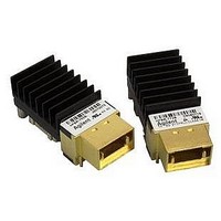
XMITTER FO 12X2.7GBD
Manufacturer
Avago Technologies US Inc.
Specifications of HFBR-772BWZ
Wavelength
850nm
Spectral Bandwidth
0.4nm
Capacitance
0.1µF
Connector Type
MTP® (MPO)
Data Rate Max
2.7Gbps
Data Transmission Distance
600m
Supply Current
320mA
Operating Temperature Range
0°C To +80°C
Peak Wavelength
850nm
Supply Voltage Range
3.135V To 3.465V
Lead Free Status / RoHS Status
Lead free / RoHS Compliant
Current - Dc Forward (if)
-
Voltage - Forward (vf) Typ
-
Voltage - Dc Reverse (vr) (max)
-
Lead Free Status / RoHS Status
Lead free / RoHS Compliant, Lead free / RoHS Compliant
Available stocks
Company
Part Number
Manufacturer
Quantity
Price

Part Number:
HFBR-772BWZ
Manufacturer:
AVAGO/安华高
Quantity:
20 000


Absolute Maximum Ratings
Notes:
1. Absolute Maximum Ratings are those values beyond which damage to the device may occur. See Reliability Data Sheet for specific
2. Between Absolute Maximum Ratings and the Recommended Operating Conditions functional performance is not intended, device
3. This is the maximum voltage that can be applied across the Transmitter Differential Data Inputs without damaging the input circuit.
4. Case Temperature is measured as indicated in Figure 3.
Recommended Operating Conditions
Notes:
1. Recommended Operating Conditions are those values outside of which functional performance is not intended, device reliability is
2. Case Temperature is measured as indicated in Figure 3.
3. The receiver has a lower cut off frequency near 100 kHz.
4. Data inputs are CML compatible. Coupling capacitors are required to block DC. V
5. Power Supply Noise is defined for the supply, VCC, over the frequency range from 500 Hz to 2500 MHz, with the recommended
5
Parameter
Storage Temperature (non-operating)
Case Temperature (operating)
Supply Voltage
Data/Control Signal Input Voltage
Transmitter Differential Data Input Voltage
Output Current (dc)
Relative Humidity (non-condensing)
m Parameter
Case Temperature
Supply Voltage
Signaling Rate per Channel
Data Input Differential Peak-to-Peak
Voltage Swing
Control Input Voltage High
Control Input Voltage Low
Power Supply Noise for
Transmitter and Receiver
Transmitter/Receiver Data
I/O Coupling Capacitors
Receiver Differential Data Output Load
reliability performance.
reliability is not implied, and damage to the device may occur over an extended period of time.
not implied, and damage to the device may occur over an extended period of time. See Reliability Data Sheet for specific reliability
performance.
State Differential Data Input Voltage and V DINL = Low State Differential Data Input Voltage.
power supply filter in place, at the supply side of the recommended filter. See Figures 5 and 6 for recommended power supply filters.
[1,2]
Symbol
N
C
R
T
V
DV
V
V
AC
DL
C
CC
IH
IL
P
|V
I
RH
Symbol
T
T
V
V
DINP-P
D
S
C
CC
I
D
[1]
|
175
Min.
0
3.135
1
2.0
V
EE
Min.
–40
–0.5
–0.5
5
0.1
100
Typ.
40
3.3
Max.
100
90
4.6
V
2
25
95
CC
DINP-P
+ 0.5
= V DINH – V DINL , where V DINH = High
1400
Max.
80
3.465
2.7
0.8
200
V
CC
Unit
mA
°C
°C
V
V
V
%
Unit
°C
V
Gbd
mV
V
V
mV
W
F
P-P
P-P
1
1, 2, 4
1, 2
1
1, 3
1
Reference
1
Reference
2, Figs. 3
Figs. 5, 6, 12
5, Figs. 5, 6
Fig. 7
Fig. 7
3
4, Figs. 7, 8
Related parts for HFBR-772BWZ
Image
Part Number
Description
Manufacturer
Datasheet
Request
R

Part Number:
Description:
RECEIVER FIBER OPTIC 600NM 5MBD
Manufacturer:
Avago Technologies US Inc.
Datasheet:

Part Number:
Description:
RECEIVER FIBER OPTIC 600NM 40KBD
Manufacturer:
Avago Technologies US Inc.
Datasheet:

Part Number:
Description:
RCVR FIBER OPTIC INTERBUS-S
Manufacturer:
Avago Technologies US Inc.
Datasheet:

Part Number:
Description:
RCVR OPT HI PERF VERS LINK HORZ
Manufacturer:
Avago Technologies US Inc.
Datasheet:
Part Number:
Description:
RCVR OPT HI PERF VERS LINK HORZ
Manufacturer:
Avago Technologies US Inc.
Datasheet:

Part Number:
Description:
XMITTER FIBER OPTIC 600NM 5MBD
Manufacturer:
Avago Technologies US Inc.
Datasheet:

Part Number:
Description:
XMITTER FIBER OPTIC 600NM 40KBD
Manufacturer:
Avago Technologies US Inc.
Datasheet:

Part Number:
Description:
XMITTER FIBER OPTIC HIGH PWR ST
Manufacturer:
Avago Technologies US Inc.
Datasheet:
Part Number:
Description:
XMITTER VERSATILE LINK HORZ
Manufacturer:
Avago Technologies US Inc.
Datasheet:
Part Number:
Description:
XMITTER VERSATILE LINK HORZ
Manufacturer:
Avago Technologies US Inc.
Datasheet:

Part Number:
Description:
XMITTER OPT HI PERFORMANCE VERT
Manufacturer:
Avago Technologies US Inc.
Datasheet:

Part Number:
Description:
Fiber Optic Transmitters, Receivers, Transceivers Versatile Link Horiz
Manufacturer:
Avago Technologies US Inc.
Datasheet:
Part Number:
Description:
Fiber Optic Transmitters, Receivers, Transceivers Versatile Link Horiz
Manufacturer:
Avago Technologies US Inc.
Datasheet:
Part Number:
Description:
Fiber Optic Transmitters, Receivers, Transceivers Versatile Link Horiz
Manufacturer:
Avago Technologies US Inc.
Datasheet:

Part Number:
Description:
FIBER OPTIC TRANSMITTER 660NM
Manufacturer:
Avago Technologies US Inc.
Datasheet: