D8505I US-Lasers Inc, D8505I Datasheet
D8505I
Manufacturer Part Number
D8505I
Description
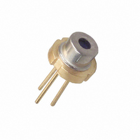
LASER DIODE 850NM 5MW
Manufacturer
US-Lasers Inc
Datasheet
1.D8505I.pdf
(1 pages)
Specifications of D8505I
Wavelength
850nm
Current Rating
65mA
Power (watts)
5mW
Package / Case
-
Voltage - Input
-
Other names
38-1030
ABSOLUTE MAXIMUM RATINGS ( Tc = 25
OPTICAL AND ELECTRICAL CHARACTERISTICS ( Tc = 25
The following precautions should be taken to avoid failure of the device;
•
•
•
•
•
DESCRIPTION
Optical Power (mW)
Operation Temp (
Storage Temp (
LD Reverse Voltage (V) VLDR
PD Reverse Voltage (V)
DESCRIPTION
Lasing Wavelength (nm)
Threshold Current (mA)
Operating Current (mA)
Operating Voltage (V)
Monitor Current (mA)
Slope Efficiency (mW/mA)
Beam Divergence
Beam Divergence
Astigmatism
ATTENTION : Observe Precautions
•
•
•
•
•
•
Index Guided MQW Structure
Wavelength : 635 nm (Typ.)
Optical Power : 5 mW CW
Threshold Current : 25 mA ( Typ. )
Package Style : TO-18 (5.6 mmØ)
Workers and workbenches should be grounded to a common
stable earth at all times when working with lasers
All equipment including power supplies, solder irons, etc. must
be grounded to a common stable earth
Power supplies should be well regulated and free of transients
Drive circuit connections should be made either by soldering or
by high reliability connectors. Clip leads such as alligator clips
are not recommended. Mechanically unreliable contacts cause
transients and destroy laser diodes
Maximum soldering temp is 250 C for a maximum of 5 seconds
High quality and high reliability components should be used
throughout the drive circuit
Static Sensitive Device
o
( m)
C)
o
C)
( )
( )
Po
Top
Tstg
VPDR
SYMBOL
www.us-lasers.com
SYMBOL
I
I
V
I
A
th
op
m
p
op
s
1 Laser Lane, Hazlehurst, GA 31539
-10 to +60
-40 to +85
RATED
VALUE
TECHNICAL DATA
30
5
2
U.S. Lasers, Inc.
Fax: 912-375-9555
Tel: 912-379-9000
Ø2.0
MIN.
0.05
835
1.8
0.3
10
15
25
8
*
Bottom View
o
C )
2
corp@us-lasers.com
3
1
•
•
•
•
TYPICAL
850
It is recommended that laser diodes be driven by an Automatic
Power Control (APC) circuit using built in monitor photodiode
in a feedback loop to maintain constant optical power output
over the full operating temperature range and throughout the
life of the device.
Always store laser diodes in static-free containers.
Never connect or disconnect any components or external
equipment such as voltmeters, to or from the device circuit
while power is on.
Leads have to be soldered to their environment without
mechanical stress. Any force during and after mounting must be
avoided
2.0
0.3
0.5
25
30
10
30
11
Pin Connection
1 - Laser Diode Cathode
2 - Laser Diode Anode
3 - Photodiode Anode
* Case and Pin No. 2 are common
1.0
Photodiode Cathode
Top View
90°
0.4
o
C )
0
MAX.
865
2.5
1.0
0.7
40
50
12
40
*
0.4
0
1.6
Po = 5mW
Po = 5mW
Po = 5mW
Po = 5mW
Po = 5mW, VR = 5
********
Po = 5mW
Po = 5mW
Po = 5mW, NA = 0.4
TEST CONDITION
1.2
Ø0.45
Ø5.6 ± .05
1
Ø4.4
Ø3.7
D8505
2
3
6.5
0
2.4
0
Related parts for D8505I
Image
Part Number
Description
Manufacturer
Datasheet
Request
R


Part Number:
Description:
LASER MODULE 650NM 5MW
Manufacturer:
US-Lasers Inc
Datasheet:

Part Number:
Description:
LASER DIODE 780NM 5MW
Manufacturer:
US-Lasers Inc
Datasheet:
Part Number:
Description:
LASER DIODE 808NM 5MW
Manufacturer:
US-Lasers Inc
Datasheet:
Part Number:
Description:
LASER DIODE 635NM 5MW
Manufacturer:
US-Lasers Inc
Datasheet:

Part Number:
Description:
LASER MODULE ADJ 650 NM 1-4.8MW
Manufacturer:
US-Lasers Inc
Datasheet: