HSMC-C265 Avago Technologies US Inc., HSMC-C265 Datasheet
HSMC-C265
Specifications of HSMC-C265
Available stocks


Related parts for HSMC-C265


HSMC-C265 Summary of contents
Page 1
... Push button backlighting x Front panel indicator x Symbol backlighting x Keypad backlighting x Microdisplays x Small message panel signage Red Orange HSMC-C120 HSML-C120 HSMC-C177 HSML-C177 HSMC-C197 HSML-C197 HSMC-C265 HSML-C265 Deep Red Package Description – Untinted, Non-diffused HSMT-C177 Untinted, Diffused HSMT-C197 Untinted, Diffused HSMT-C265 Untinted, Non-diffused ...
Page 2
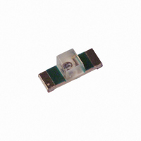
Package Dimensions CATHODE MARK 2.00 (0.079) DIFFUSED EPOXY PC BOARD 0.16 (0.006) CATHODE LINE 0.40 ± 0.15 (0.016 ± 0.006) (0.016 ± 0.006) 1.10 (0.043) MIN. SOLDERING TERMINAL HSMx-C177 3.4 (0.134) LED DIE GREEN SOLDER MASK 1.2 UNDIFFUSED (0.047) EPOXY ...
Page 3
... Soldering Temperature Notes: 1. Derate linearly as shown in Figure 4. Electrical Characteristics 25˚C A Forward Voltage V (Volts Part Number Typ. HSMA-C120 1.9 HSMA-C177/197 1.9 HSMA-C265 1.9 HSMC-C120 1.9 HSMC-C177/197 1.9 HSMC-C265 1.9 HSML-C120 1.9 HSML-C177/197 1.9 HSML-C265 1.9 HSMT-C177/197 1.9 HSMT-C265 1.9 V Tolerance: ± 0 HSMx-Cxxx Units ˚ ...
Page 4
... A Part Number Color HSMA-C120 Amber HSMA-C177/197 Amber HSMA-C265 Amber HSMC-C120 Red HSMC-C177/197 Red HSMC-C265 Red HSML-C120 Orange HSML-C177/197 Orange HSML-C265 Orange HSMT-C177/197 Deep Red HSMT-C265 Deep Red Notes: 1. The luminous intensity measured at the peak of the spatial radiation pattern which may not be aligned with the mechanical axis of the V lamp package ...
Page 5
Color Bin Limits Orange Color Bins Dom. Wavelength (nm) Bin ID Min. A 597.0 B 600.0 C 603.0 D 606.0 E 609.0 F 612.0 Tolerance: ± Amber Color Bins Dom. Wavelength (nm) Bin ID Min. A 582.0 B ...
Page 6
RED AMBER 80 AS DEEP 70 RED AS 60 ORANGE 500 550 600 650 700 WAVELENGTH – nm Figure 1. Relative intensity vs. wavelength HSMx-C120/177/197 15 HSMx-C265 ...
Page 7
ANGLE Figure 6. Relative intensity vs. angle for HSMx-C177/197. 100 ...
Page 8
Figure 12. Recommended soldering pattern for HSMx-C120. USER FEED DIRECTION PRINTED LABEL Figure 14. Reeling orientation. 3.0 ± 0.5 (0.118 ± 0.020) 178.40 ± 1.00 (7.024 ± 0.039) 4.0 ± ...
Page 9
DIM. A (SEE TABLE 1) DIM. B (SEE TABLE 1) 2.00 ± 0.05 (0.079 ± 0.002) HSMx-C120 POSITION IN CARRIER TAPE DIM. A (SEE TABLE 1) DIM. B HSMx-C120 (SEE TABLE 1) R 0.5 ± 0.05 (0.020 ± ...
Page 10
END THERE SHALL BE A MOUNTED WITH MINIMUM OF 160 mm COMPONENTS (6.3 INCH) OF EMPTY COMPONENT POCKETS SEALED WITH COVER TAPE. Figure 17. Tape leader and trailer dimensions. Convective IR Reflow Soldering For more information on IR reflow soldering, ...