HLMP-4000 Avago Technologies US Inc., HLMP-4000 Datasheet - Page 6
HLMP-4000
Manufacturer Part Number
HLMP-4000
Description
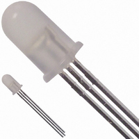
LED 5MM BICOLOR GREEN/HER DIFF
Manufacturer
Avago Technologies US Inc.
Type
Bi-Colorr
Specifications of HLMP-4000
Viewing Angle
65°
Package / Case
Radial - 3 Lead
Color
Green, Red
Millicandela Rating
4.2mcd Green, 2.1mcd Red
Current - Test
10mA
Wavelength - Dominant
570nm, 626nm
Wavelength - Peak
568nm, 635nm
Voltage - Forward (vf) Typ
2.2V Green, 1.9V Red
Lens Type
Diffused
Lens Style/size
Round, 5mm, T-1 3/4
Height
8.81mm
Mounting Type
Through Hole
Resistance Tolerance
570nm, 626nm
Led Size
T-1 3/4
Illumination Color
Green, High Efficiency Red
Lens Color/style
Diffused
Operating Voltage
2.2 V, 1.9 V
Wavelength
570 nm, 626 nm
Luminous Intensity
4.2 mcd, 2.1 mcd
Operating Current
10 mA
Lens Dimensions
5 mm
Lens Shape
Dome
Maximum Operating Temperature
+ 100 C
Minimum Operating Temperature
- 20 C
Mounting Style
Through Hole
Current, Forward
90 mA (Peak)
Diameter, Mounting Hole
0.22 in.
Package Type
T-1 3⁄4
Temperature, Operating, Maximum
100 °C
Temperature, Operating, Minimum
-20 °C
Termination
Radial Leaded
Voltage, Rating
1.9 V (Typ.)
Voltage, Reverse
5 V
Wavelength, Peak
635 nm (Typ.)
Emitting Color
Yellow Green/Red
Test Current (it)
10mA
Forward Current
30mA
Dominant Wave Length
570/626nm
Forward Voltage
3/2.6V
Product Length (mm)
6.1mm
Product Height (mm)
9.19mm
Product Depth (mm)
6.1mm
Mounting
Through Hole
Peak Wavelength
568/635nm
Shape Type
Circular
Main Category
Standard LED
Number Of Elements
2
Pin Count
2
Operating Temperature Classification
Commercial
Operating Temp Range
-20C to 100C
Reverse Voltage
5V
Power Dissipation
135mW
Bulb Size
T-1 3/4 (5mm)
Led Color
Red / Green
Luminous Intensity / Color
R 2.1mcd / G 4.2mcd
Forward Voltage / Color
R 1.9V / G 2.2V
Led Mounting
Through Hole
Rohs Compliant
Yes
Lead Free Status / RoHS Status
Lead free / RoHS Compliant
Luminous Flux @ Current - Test
-
Lead Free Status / Rohs Status
Lead free / RoHS Compliant
Other names
516-1287
Available stocks
Company
Part Number
Manufacturer
Quantity
Price
Company:

Part Number:
HLMP-4000
Manufacturer:
AGILENT
Quantity:
15
Company:
Part Number:
HLMP-4000
Manufacturer:
FAIRCHIL
Quantity:
40 000
Part Number:
HLMP-4000
Manufacturer:
AVAGO/安华高
Quantity:
20 000
Company:
Part Number:
HLMP-4000#002
Manufacturer:
AVAGO
Quantity:
50 000
Company:
Part Number:
HLMP-4000#010
Manufacturer:
AVAGO
Quantity:
50 000


Precautions
Lead Forming
• The leads of an LED lamp may be preformed or cut to
• If lead forming is required before soldering, care must
• It is recommended that tooling made to precisely
Soldering Conditions
• Care must be taken during PCB assembly and
• The closest LED is allowed to solder on board is 1.59
• Recommended soldering conditions:
Figure 8. Recommended wave soldering profile.
6
length prior to insertion and soldering into PC board.
be taken to avoid any excessive mechanical stress
induced to LED package. Otherwise, cut the leads of
LED to length after soldering process at room
temperature. The solder joint formed will absorb the
mechanical stress of the lead cutting from traveling to
the LED chip die attach and wirebond.
form and cut the leads to length rather than rely upon
hand operation.
soldering process to prevent damage to LED
component.
mm below the body (encapsulant epoxy) for those
parts without standoff.
Pre-heat Temperature
Pre-heat Time
Peak Temperature
Dwell Time
250
200
150
100
50
30
0
10
FLUXING
TURBULENT WAVE
PREHEAT
20
30
TIME – SECONDS
40
Wave Soldering
105 C Max.
30 sec Max.
250 C Max.
3 sec Max.
50
60
70
LAMINAR WAVE
HOT AIR KNIFE
80
90
Manual Solder
Dipping
–
–
260 C Max.
5 sec Max.
100
CONVEYOR SPEED = 1.83 M/MIN (6 FT/MIN)
PREHEAT SETTING = 150 C (100 C PCB)
SOLDER WAVE TEMPERATURE = 245 C
AIR KNIFE AIR TEMPERATURE = 390 C
AIR KNIFE DISTANCE = 1.91 mm (0.25 IN.)
AIR KNIFE ANGLE = 40
SOLDER: SN63; FLUX: RMA
NOTE: ALLOW FOR BOARDS TO BE
SUFFICIENTLY COOLED BEFORE EXERTING
MECHANICAL FORCE.
BOTTOM SIDE
OF PC BOARD
TOP SIDE OF
PC BOARD
• Wave soldering parameter must be set and
• If necessary, use fixture to hold the LED component
• Proper handling is imperative to avoid excessive
• Special attention must be given to board fabrication,
• Recommended PC board plated through hole sizes for
Note: Refer to application note AN1027 for more
information on soldering LED components.
maintained according to recommended temperature
and dwell time in the solder wave. Customer is
advised to periodically check on the soldering profile
to ensure the soldering profile used is always
conforming to recommended soldering condition.
in proper orientation with respect to the PCB during
soldering process.
thermal stresses to LED components when heated.
Therefore, the soldered PCB must be allowed to cool
to room temperature, 25 C, before handling.
solder masking, surface plating and lead holes size
and component orientation to assure solderability.
LED component leads:
LED Component
Lead Size
0.457 x 0.457 mm
(0.018 x 0.018 inch)
0.508 x 0.508 mm
(0.020 x 0.020 inch)
Diagonal
0.646 mm
(0.025 inch)
0.718 mm
(0.028 inch)
Plated Through
Hole Diameter
0.976 to 1.078 mm
(0.038 to 0.042 inch)
1.049 to 1.150 mm
(0.041 to 0.045 inch)
Related parts for HLMP-4000
Image
Part Number
Description
Manufacturer
Datasheet
Request
R

Part Number:
Description:
LED 5MM 635NM HE RED WATER CLEAR
Manufacturer:
Avago Technologies US Inc.
Datasheet:

Part Number:
Description:
LED 5MM 639NM RED WATER CLEAR
Manufacturer:
Avago Technologies US Inc.
Datasheet:

Part Number:
Description:
LED LT BAR 19.05X3.81MM SGL YLW
Manufacturer:
Avago Technologies US Inc.
Datasheet:

Part Number:
Description:
LED Lamp
Manufacturer:
Avago Technologies US Inc.
Datasheet:

Part Number:
Description:
LED T1 3/4 5MM WHT PREC OPT PREF
Manufacturer:
Avago Technologies US Inc.
Datasheet:
Part Number:
Description:
LED, T-1 3/4, RED, 8.6MCD, 626NM
Manufacturer:
Avago Technologies US Inc.
Datasheet:

Part Number:
Description:
LED 5MM FLAT TOP INGAN WHITE
Manufacturer:
Avago Technologies US Inc.
Datasheet:
Part Number:
Description:
LED 5MM FLAT TOP INGAN WHITE
Manufacturer:
Avago Technologies US Inc.
Datasheet:
Part Number:
Description:
LED 5MM FLAT TOP INGAN WHITE
Manufacturer:
Avago Technologies US Inc.
Datasheet:
Part Number:
Description:
LED 5MM FLAT TOP INGAN WHITE
Manufacturer:
Avago Technologies US Inc.
Datasheet:

Part Number:
Description:
LED T 1 3/4 OR 5MM AMBER
Manufacturer:
Avago Technologies US Inc.
Datasheet:

Part Number:
Description:
LED T1-3/4 SUPER BRIGHT GREEN
Manufacturer:
Avago Technologies US Inc.
Part Number:
Description:
LED LIGHT BAR, 4, RED, 23MCD
Manufacturer:
Avago Technologies US Inc.
Datasheet:
Part Number:
Description:
LED LIGHT BAR, 4, GREEN, 25MCD
Manufacturer:
Avago Technologies US Inc.
Datasheet:
Part Number:
Description:
LED, T-1 3/4, BLUE, 1500MCD, 470NM
Manufacturer:
Avago Technologies US Inc.
Datasheet: