HLMP-6400-F0021 Avago Technologies US Inc., HLMP-6400-F0021 Datasheet - Page 11
HLMP-6400-F0021
Manufacturer Part Number
HLMP-6400-F0021
Description
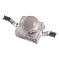
LED DOME GAP YLW YOKE
Manufacturer
Avago Technologies US Inc.
Type
Uni-Colorr
Datasheet
1.HLMP-6505-L0021.pdf
(16 pages)
Specifications of HLMP-6400-F0021
Viewing Angle
90°
Mounting Type
Through Hole
Color
Yellow
Millicandela Rating
9mcd
Current - Test
10mA
Wavelength - Dominant
585nm
Wavelength - Peak
583nm
Voltage - Forward (vf) Typ
2V
Lens Type
Diffused, Yellow Tinted
Lens Style/size
Round, 1.78mm
Package / Case
2-SMD, Yoke Bend
Size / Dimension
2.08mm L x 2.21mm W
Height
2.92mm
Resistance Tolerance
585nm
Bulb Size
1.9mm
Led Color
Yellow
Luminous Intensity
9mcd
Forward Current If
20mA
Forward Voltage
2V
Led Mounting
SMD
Lens Shape
Round
Wavelength Typ
585nm
Package Type
Flat Top
Emitting Color
Amber
Test Current (it)
10mA
Forward Current
20mA
Dominant Wave Length
585nm
Product Length (mm)
2.34mm
Product Height (mm)
2.92mm
Product Depth (mm)
2.21mm
Mounting
Surface Mount
Peak Wavelength
583nm
Shape Type
Circular
Main Category
Resistor LED
Number Of Elements
1
Pin Count
2
Operating Temperature Classification
Industrial
Operating Temp Range
-40C to 85C
Reverse Voltage
5V
Lens Dimensions
1.91x1.91x1.4mm
Lead Free Status / RoHS Status
Lead free / RoHS Compliant
Luminous Flux @ Current - Test
-
Lead Free Status / Rohs Status
Compliant
Available stocks
Company
Part Number
Manufacturer
Quantity
Price
Company:

Part Number:
HLMP-6400-F0021
Manufacturer:
AVAGO
Quantity:
40 000
Company:
Part Number:
HLMP-6400-F0021
Manufacturer:
AVAGO
Quantity:
50 000


Emerald Green
Device
HLMP-
P605-F00xx
Q600-F00xx
Q605-F00xx
All
P605
Q60x
P605/Q600
Note:
1. Please refer to Application Note 1061 for information comparing standard green and emerald green light output degradation.
11
[1]
Parameter
Luminous Intensity
Forward Voltage
Reverse Breakdown Voltage
Included Angle Between
Half Intensity Points
Peak Wavelength
Dominant Wavelength
Spectral Line Half Width
Speed of Response
Capacitance
Thermal Resistance
Luminous Efficacy
[4]
[2]
[3]
Symbol
I
V
V
2q
l
l
Dl
t
C
Rq
h
V
s
F
R
PEAK
d
V
1
J-PIN
1/2
/
2
Min.
1.0
1.0
1.0
5.0
Typ.
1.5
1.5
7.5
2.2
125
90
558
560
24
3100
35
170
656
Max.
3.0
Units
mcd
V
V
Deg.
nm
nm
nm
ns
pF
lm/W
C/W
Test Conditions
I
I
I
Measured at Peak
V
Junction-to-Cathode Lead
F
F
R
F
= 10 mA
= 10 mA
= 100 A
= 0; f = 1 MHz
Related parts for HLMP-6400-F0021
Image
Part Number
Description
Manufacturer
Datasheet
Request
R

Part Number:
Description:
LED DOME 583NM YLW DIFF RA AXIAL
Manufacturer:
Avago Technologies US Inc.
Datasheet:

Part Number:
Description:
LED DOME 583NM YLW DIFF AXIAL
Manufacturer:
Avago Technologies US Inc.
Datasheet:

Part Number:
Description:
LED DOME GAP YLW R/BEND
Manufacturer:
Avago Technologies US Inc.
Datasheet:
Part Number:
Description:
LED DOME GAP YLW
Manufacturer:
Avago Technologies US Inc.
Datasheet:
Part Number:
Description:
LED DOME GAP YLW Z-BEND
Manufacturer:
Avago Technologies US Inc.
Datasheet:

Part Number:
Description:
LED, 1.91MM, YELLOW, 9MCD, 585NM
Manufacturer:
Avago Technologies US Inc.
Datasheet:
Part Number:
Description:
SUBMINIATURE LED LAMP
Manufacturer:
Avago Technologies US Inc.
Datasheet:

Part Number:
Description:
LED DOME GAASP GW
Manufacturer:
Avago Technologies US Inc.
Datasheet:

Part Number:
Description:
LED DOME 655NM RED DIFF AXIAL
Manufacturer:
Avago Technologies US Inc.
Datasheet:
Part Number:
Description:
LED FLAT TOP GAASP RED GW
Manufacturer:
Avago Technologies US Inc.
Datasheet:
Part Number:
Description:
LED FLAT TOP GAASP RED Z-BEND
Manufacturer:
Avago Technologies US Inc.
Datasheet:
Part Number:
Description:
Standard LED - SMD Poly Dome Red
Manufacturer:
Avago Technologies US Inc.

Part Number:
Description:
LED DOME 635NM DIFF HER AXIAL
Manufacturer:
Avago Technologies US Inc.
Datasheet:
Part Number:
Description:
LED FLAT TOP GAP ORN DIFFUSED
Manufacturer:
Avago Technologies US Inc.
Datasheet:
Part Number:
Description:
LED DOME RLED GAP HER GW
Manufacturer:
Avago Technologies US Inc.
Datasheet: