HSMF-C113 Avago Technologies US Inc., HSMF-C113 Datasheet - Page 3
HSMF-C113
Manufacturer Part Number
HSMF-C113
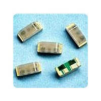
Description
LED CHIP RGB 2.5X1.0X1.0MM SMD
Manufacturer
Avago Technologies US Inc.
Type
Tri-Colorr
Datasheet
1.HSMF-C113.pdf
(8 pages)
Specifications of HSMF-C113
Viewing Angle
120° Red, 125° Green, 125° Blue
Package / Case
4-SMD, No Leads
Mounting Type
Surface Mount, Right Angle
Color
Red, Green, Blue (RGB)
Lens Style/size
Rectangle, 2.1mm x 1mm
Voltage - Forward (vf) Typ
1.9V Red, 2.0V Green, 3.4V Blue
Millicandela Rating
80mcd Red, 50mcd Green, 60mcd Blue
Luminous Flux @ Current - Test
251 mlm Red, 169 mlm Green, 203 mlm Blue
Current - Test
20mA
Lens Type
Diffused
Wavelength - Peak
637nm, 570nm, 468nm
Resistance Tolerance
626nm, 572nm, 470nm
Led Size
2.5 mm x 1 mm
Illumination Color
Red, Green, Blue
Lens Color/style
Diffused
Operating Voltage
1.9 V, 2 V, 3.4 V
Wavelength
626 nm, 572 nm, 470 nm
Luminous Intensity
80 mcd, 50 mcd, 60 mcd
Mounting Style
SMD/SMT
Operating Current
20 mA
Lens Dimensions
2.1 mm x 1 mm
Lens Shape
Rectangular
Maximum Operating Temperature
+ 85 C
Minimum Operating Temperature
- 40 C
Peak Wavelength
637 nm, 670 nm, 468 nm
Package Type
Chip Led
Emitting Color
Blue/Yellow Green/Red
Test Current (it)
20mA
Forward Current
20mA
Dominant Wave Length
470/572/626nm
Forward Voltage
3.9/2.6/2V
Product Length (mm)
2.5mm
Product Height (mm)
1mm
Product Depth (mm)
1mm
Mounting
Surface Mount
Shape Type
Rectangular
Chip Material
InGaN/AlGaInP/AlGaInP
Main Category
Chip LED
Number Of Elements
3
Pin Count
4
Operating Temperature Classification
Industrial
Operating Temp Range
-40C to 85C
Reverse Voltage
5V
Power Dissipation
59/39/36mW
Lead Free Status / RoHS Status
Lead free / RoHS Compliant
Lead Free Status / RoHS Status
Lead free / RoHS Compliant, Lead free / RoHS Compliant
Available stocks
Company
Part Number
Manufacturer
Quantity
Price
Company:

Part Number:
HSMF-C113
Manufacturer:
MURATA
Quantity:
30
Company:
Part Number:
HSMF-C113
Manufacturer:
AVAGO
Quantity:
50 000


Absolute Maximum Ratings at T
Notes:
1. Applies when single LED is lit up.
2. Applies when all 3 LEDs are lit up simultaneously.
3. Derate linearly as shown in Figure 4.
4. Drive currents above 5 mA are recommended for best long term performance.
Electrical Characteristics at T
Notes:
1.Vf tolerance : ±0.1V
Optical Characteristics at T
Notes:
1. The luminous intensity I
2. The dominant wavelength, λ
3. θ
3
Parameter
DC Forward Current
Power Dissipation
DC Forward Current
Power Dissipation
Reverse Voltage (I
LED Junction Temperature
Operating Temperature Range
Storage Temperature Range
Soldering Temperature
Part Number
AlInGaP Red
AlInGaP Green
InGaN Green
InGaN Blue
Part Number
AlInGaP Red
AlInGaP Green
InGaN Green
InGaN Blue
LED package.
1/2
is the off-axis angle where the luminous intensity is ½ the peak intensity.
R
[1]
[2
= 100mA)
]
[1,3]
[2]
V
28.5
Min.
28.5
18.0
71.5
is measured at the peak of the spatial radiation pattern which may not be aligned with the mechanical axis of the
Luminous Intensity
Typ.
3.4
1.9
2.0
3.4
A
Forward Voltage
d
= 25°C
, is derived from the CIE Chromaticity Diagram and represents the perceived color of the device.
A
@ I
I
VF (Volts)
V [1]
= 25°C
@ 20mA
F
A
= 20mA
= 25°C
(mcd)
170.0
60.0
80.0
50.0
Typ.
[1]
Max.
3.9
2.0
2.6
3.9
AlInGaP Red
20
48
15
36
95
5
Peak Wavelength
Reverse Breakdown
l
@ I
peak
Typical
V
468
R
637
570
523
R
= 100mA
Min.
(Volts)
(nm)
See IR soldering profile (Figure 6 & 7)
5
5
5
5
AlInGaP Green
20
52
15
39
95
5
Color, Dominant Wave-
-40 to +85
-40 to +85
l
@ V
d [2]
length
Typical
470
626
572
525
Capacitance
InGaN Green
F
= 0, f = 1MHz
(nm)
C(pF),
Typ.
65
12
15
65
20
78
15
59
95
5
(Degrees)
Viewing
2q
Typical
Angle
125
120
125
125
1/2 [3]
InGaN Blue
Thermal Resistance
20
78
15
59
95
5
Rq
J-PIN
400
Typ.
550
300
400
Luminous Ef-
h
(°C/W)
V
Typical
ficacy
155
570
443
(lm/W)
89
Units
mW
mW
mA
mA
°C
°C
°C
V
Related parts for HSMF-C113
Image
Part Number
Description
Manufacturer
Datasheet
Request
R

Part Number:
Description:
LED CHIP GAP GREEN/YELLOW SMD
Manufacturer:
Avago Technologies US Inc.
Datasheet:

Part Number:
Description:
LED BICOLOR YLW/GN DIFF 1210 SMD
Manufacturer:
Avago Technologies US Inc.
Datasheet:

Part Number:
Description:
LED CHIP GRN/ORN 3.2X2.7MM SMD
Manufacturer:
Avago Technologies US Inc.
Datasheet:

Part Number:
Description:
LED IND RED/GRN TOP MOUNT 4PLCC
Manufacturer:
Avago Technologies US Inc.
Datasheet:
Part Number:
Description:
LED IND YLW/YGRN TOP MOUNT 4PLCC
Manufacturer:
Avago Technologies US Inc.
Datasheet:

Part Number:
Description:
LED CHIPLED AMB/BLUE DIFF 0603
Manufacturer:
Avago Technologies US Inc.
Datasheet:
Part Number:
Description:
LED CHIPLED RED/GRN DIFF 0603
Manufacturer:
Avago Technologies US Inc.
Datasheet:
Part Number:
Description:
LED RED/GREEN/BLUE 40MCD 5V SMD
Manufacturer:
Avago Technologies US Inc.
Datasheet:
Part Number:
Description:
Standard LED - SMD Red/YGrn/Blue Tri-Color
Manufacturer:
Avago Technologies US Inc.
Datasheet:

Part Number:
Description:
LED CHIP RGB 3.2X2.7X1.1MM SMD
Manufacturer:
Avago Technologies US Inc.
Datasheet:

Part Number:
Description:
LED BICOLOR GN/HER DIFF 1210 SMD
Manufacturer:
Avago Technologies US Inc.
Datasheet:

Part Number:
Description:
LED BICOLOR HER/GN DIFF 0603 SMD
Manufacturer:
Avago Technologies US Inc.
Datasheet:
Part Number:
Description:
LED IND RED/YLW TOP MOUNT 4PLCC
Manufacturer:
Avago Technologies US Inc.
Datasheet:
Part Number:
Description:
LED IND RED/EGRN TOP MOUNT 4PLCC
Manufacturer:
Avago Technologies US Inc.
Datasheet:
Part Number:
Description:
LED IND ORN/YGRN TOP MOUNT 4PLCC
Manufacturer:
Avago Technologies US Inc.
Datasheet: