LT E67C-T2V1-35 OSRAM Opto Semiconductors Inc, LT E67C-T2V1-35 Datasheet
LT E67C-T2V1-35
Specifications of LT E67C-T2V1-35
LTE67CT2V135
Q65110A0274


Related parts for LT E67C-T2V1-35


LT E67C-T2V1-35 Summary of contents
Page 1
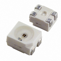
... Power TOPLED Enhanced optical Power LED (ATON LB E67C, LV E67C, LT E67C Vorläufige Daten / Preliminary Data Besondere Merkmale • Gehäusetyp: weißes P-LCC-4 Gehäuse • Besonderheit des Bauteils: mehr Licht durch erhöhten optischen Wirkungsgrad; höhere Umgebungstemperatur bei gleichem Strom im ® ...
Page 2
... LV E67C-T2V1-35 LT E67C-S2T2-35 true green LT E67C-T2V1-35 Anm.: -35 gesamter Farbbereich, Lieferung in Einzelgruppen (siehe Seite 5) Die Standardlieferform von Serientypen beinhaltet eine untere bzw. eine obere Familiengruppe, die aus nur 3 bzw. 4 Halbgruppen besteht. Einzelne Halbgruppen sind nicht erhältlich. In einer Verpackungseinheit / Gurt ist immer nur eine Halbgruppe enthalten. ...
Page 3
... Power consumption Wärmewiderstand Thermal resistance Sperrschicht/Umgebung Junction/ambient Sperrschicht/Lötpad Junction/solder point Montage auf PC-Board FR 4 (Padgröß mounted on PC board FR 4 (pad size 1) für kurzzeitigen Betrieb geeignet / suitable for short term application 2003-05-26 LB E67C, LV E67C, LT E67C Symbol Symbol stg ...
Page 4
... V (typ.) F (max (typ.) R (max (typ.) TC peak peak (typ.) TC dom dom TC (typ (typ.) opt 4 LB E67C, LV E67C, LT E67C Werte Values 464 501 520 469 503 525 ± 6 ± 6 ± 120 120 120 4.1 3.8 3.8 4.6 4.6 4.6 0.01 0.01 0.01 ...
Page 5
... Halbgruppe Half Group E67C, LV E67C, LT E67C Lichtstrom Luminous Flux (mlm 190 (typ.) 90 240 (typ.) 300 (typ.) 380 (typ.) 480 (typ.) 600 (typ ...
Page 6
... °C, I rel A F 500 550 20˚ 10˚ 0˚ 1.0 0.8 0.6 0.4 0.2 0 0.6 0.4 0˚ E67C, LV E67C, LT E67C = blue verde true green 600 650 20˚ 40˚ 60˚ 80˚ OHL00492 nm 700 OHL01660 100˚ 120˚ ...
Page 7
... T temp. ambient 2003-05-26 Relative Lichtstärke Relative Luminous Intensity °C A OHL01619 (30 mA) 5 Maximal zulässiger Durchlassstrom F Max. Permissible Forward Current OHL01569 ˚C 100 E67C, LV E67C, LT E67C V(30 mA verde true green blue - blue 20 verde, true green temp. solder point S ...
Page 8
... T ) Dominante Wellenlänge A Dominant Wavelength LB OHL01637 40 60 ˚C 100 Dominante Wellenlänge dom F Dominant Wavelength LV OHL00882 80 mA 120 E67C, LV E67C, LT E67C dom , °C A 474 nm dom 473 472 471 blue 470 469 468 467 dom , °C A 516 nm dom 512 510 508 ...
Page 9
... Permissible Pulse Handling Capability = 25 °C, LB Duty cycle A OHL01578 Zulässige Impulsbelastbarkeit Permissible Pulse Handling Capability Duty cycle = 25 ° OHL01583 0.005 0.01 0.02 0. E67C, LV E67C, LT E67C parameter ° 0. 0.25 T 0.20 0. 0.005 0.01 0.10 0.02 0.05 0.2 0.1 0.05 0 parameter ° 0. 0.25 T 0.20 ...
Page 10
... Maße werden wie folgt angegeben: mm (inch) / Dimensions are specified as follows: mm (inch). Gewicht / Approx. weight 2003-05-26 3.0 (0.118) 2.6 (0.102) 2.3 (0.091) 2.1 (0.083) 0.8 (0.031) 0.6 (0.024 0.1 (0.004) typ E67C, LV E67C, LT E67C 2.1 (0.083) 1.7 (0.067) 0.9 (0.035) 0.7 (0.028) 0.6 (0.024) 0.4 (0.016) 0.18 (0.007) 0.12 (0.005) GPLY6991 ...
Page 11
... IR Reflow Soldering Profile (acc. to IPC 9501) 300 ˚C 250 T 200 150 100 Ramp-up rate K/s 50 Defined for Preconditioning: 2-3 K 2003-05-26 (nach IPC 9501) 120 to 180 s 100 11 LB E67C, LV E67C, LT E67C 240-245 ˚C 10-40 s 183 ˚C Ramp-down rate K/s Defined for Preconditioning K/s 150 200 t OHLY0597 s 250 ...
Page 12
... CECC 00802) 300 C 250 T 235 C ... 260 C 200 1. Welle 1. wave 150 ca 200 K/s 100 C ... 130 C 100 2003-05- Welle 2. wave 2 K/s 5 K/s Zwangskühlung 2 K/s forced cooling 100 12 LB E67C, LV E67C, LT E67C Normalkurve standard curve Grenzkurven limit curves 150 200 t OHLY0598 s 250 ...
Page 13
... Maße werden wie folgt angegeben: mm (inch) / Dimensions are specified as follows: mm (inch). 2003-05-26 IR Reflow Löten IR Reflow Soldering 3.3 (0.130) Anode Cu Fläche / 16 mm per pad Cu-area Lötstoplack Solder resist 13 LB E67C, LV E67C, LT E67C Fläche darf elektrisch nicht beschaltet werden. Do not use this area for electrical contact. 3.3 (0.130) Kathode/ Cathode < OHLPY440 ...
Page 14
... Verpackungseinheit 2000/Rolle, ø180 mm oder 8000/Rolle, ø330 mm or 8000/reel, ø330 mm 4 (0.157) 2 (0.079) 4 (0.157) 2.9 (0.114 E67C, LV E67C, LT E67C Fläche darf elektrisch nicht beschaltet werden. Do not use this area for electrical contact. Kathode/ 0.5 (0.020) Cathode Cu Fläche / > per pad Cu-area Lötstoplack ...
Page 15
... Life support devices or systems are intended ( implanted in the human body, or (b) to support and/or maintain and sustain human life. If they fail reasonable to assume that the health of the user may be endangered. 2003-05-26 LB E67C, LV E67C, LT E67C 2 with the express written approval of OSRAM OS. 15 Date of change ...