LHGB T686-KL-1+KL-1+JK-1 OSRAM Opto Semiconductors Inc, LHGB T686-KL-1+KL-1+JK-1 Datasheet
LHGB T686-KL-1+KL-1+JK-1
Specifications of LHGB T686-KL-1+KL-1+JK-1
Q2056169
Q62703Q5771


Related parts for LHGB T686-KL-1+KL-1+JK-1


LHGB T686-KL-1+KL-1+JK-1 Summary of contents
Page 1
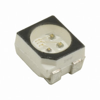
... Hyper Multi TOPLED Hyper-Bright LED LHGB T686 Vorläufige Daten / Preliminary Data Abgekündigt nach OS-PD-2005-002 - wird durch LATB T686 ersetzt werden Obsolete acc. to OS-PD-2005-002 - will be replaced by LATB T686 Besondere Merkmale • Gehäusetyp: weißes P-LCC-4 Gehäuse, Kontrasterhöhung durch schwarze Oberfläche (RGB-Displays) • ...
Page 2
... Obsolete acc. to OS-PD-2005-002 - will be replaced by LATB T686 Letzte Bestellung / Last Order: 2005-08-31 Letzte Lieferung / Last Delivery: 2006-02-28 Bestellinformation Ordering Information Typ Type LHGB T686-KL-1+KL-1+JK-1 Anm.: -1 Gesamter Farbbereich (siehe Seite 4) Note: -1 Total color tolerance range (see page 4) 2005-03-03 1) Seite 19 Lichtstärke 1) page 19 ...
Page 3
... 500 tot R 1 chip on 480 chips on 680 chip on R 260 chips on R 370 LHGB T686 Werte Einheit Values Unit green blue – 40 … + 100 °C – 40 … + 100 °C + 100 ° 500 200 480 580 K/W 770 820 K/W 260 ...
Page 4
... F V (max.) F (typ (max (typ.) λpeak peak peak TC (typ.) λdom dom dom TC (typ η (typ.) opt 4 LHGB T686 Werte Einheit Values Unit hyper green blue red 660 572 428 nm 645 570 465 nm ± 9 ± 6 ± 120 120 120 Grad deg. 1.75 2 ...
Page 5
... Serientypen beinhaltet Helligkeits- Wellenlänge gruppe (keine Gruppierung) Brightness Wavelength Group (no grouping) (green) (green LHGB T686 6) Seite 19 Lichtstrom 6) page 19 Luminous Flux Φ (mlm (typ.) 27 (typ.) 45 (typ.) eine Familiengruppe. Einzelne Helligkeits- Wellenlänge gruppe (keine Gruppierung) Brightness ...
Page 6
... Seite 19 6) page 19 V λ green 450 500 20˚ 10˚ 0˚ ϕ 1.0 0.8 0.6 0.4 0.2 0 0.6 0.4 0˚ 6 hyper-red 550 600 650 20˚ 40˚ 60˚ 80˚ LHGB T686 OHL01366 nm 700 λ OHL01660 100˚ 120˚ ...
Page 7
... Relative Lichtstärke Relative Luminous Intensity OHL01360 green 3 Relative Lichtstärke Relative Luminous Intensity OHL00432 Seite °C V(10 mA (10 mA blue hyper-red green - Seite V(25 ° (25 ˚C) 1.6 1.2 green 0.8 hyper-red 0 LHGB T686 6) 7) page 19 OHL01368 page 19 OHL01369 blue 60 80 ˚C 100 T j ...
Page 8
... Maximal zulässiger Durchlassstrom Max. Permissible Forward Current OHL00100 ˚C 100 T A Maximal zulässiger Durchlassstrom Max. Permissible Forward Current OHL00101 ˚C 100 chips on OHL00106 green hyper-red blue ˚C 100 chips on OHL00107 green hyper-red blue ˚C 100 LHGB T686 ...
Page 9
... Duty cycle A blue (3 Chips on) OHL00117 0.005 0.01 0.02 0.05 0.1 0.2 0 parameter ° 0.20 0. 0.005 0.01 0.10 0.02 0.05 0.1 0.2 0.5 0. parameter °C A 0.040 0.025 0.020 0.015 0.010 0.005 LHGB T686 OHL01434 OHL00118 0.005 0.01 0.02 0.05 0.1 0.2 0 ...
Page 10
... Zulässige Impulsbelastbarkeit Permissible Pulse Handling Capability Duty cycle D = parameter, T green/hyper-red (1 Chip on 0.005 0.01 0.02 0.05 0 2005-03- Zulässige Impulsbelastbarkeit F p Permissible Pulse Handling Capability = 25 °C Duty cycle A green/hyper-red (1 Chip on) OHL01686 parameter ° 0.005 0.02 0.1 0.2 0 LHGB T686 OHL00104 ...
Page 11
... F p Permissible Pulse Handling Capability = 25 °C Duty cycle A green (3 Chips on) OHL00108 = Zulässige Impulsbelastbarkeit F p Permissible Pulse Handling Capability = 25 °C Duty cycle A hyper-red (3 Chips on) OHL00102 = parameter ° 0.005 0.02 0.1 0.2 0 parameter ° 0.005 0.02 0.1 0.2 0 LHGB T686 OHL00109 OHL00103 ...
Page 12
... The color coordinates of the mixed light can be expected within the area of the color triangle marked a). The achromatic point (x = 0.33 0.33) is marked “+”. 2005-03-03 520 530 540 550 560 570 a) + 0.1 0.2 0.3 0.4 0.5 12 OHA01435 580 590 600 610 620 630 0.6 0.7 0.8 0.9 LHGB T686 ...
Page 13
... Seite 19 8) page 19 4 (0.157) 2 (0.079) 4 (0.157) 2.9 (0.114) 13 2.1 (0.083) 1.7 (0.067) 0.9 (0.035) 0.7 (0.028 0.6 (0.024) Circuit Diagram 0.4 (0.016) 0.18 (0.007) Hyper-red( Blue (B) Green ( Verpackungseinheit 8000/Rolle, ø330 mm Packing unit 8000/reel, ø330 LHGB T686 C C GPLY6900 C A OHAY0095 ...
Page 14
... Solder resist 8) Seite 19 Wellenlöten (TTW) 8) page 19 TTW Soldering 3.5 (0.138) 2.8 (0.110) Cu Fläche / > per pad Cu-area Lötstoplack Solder resist 14 3.3 (0.130) 0.4 (0.016 < Cu Fläche / 12 mm per pad Cu-area OHLPY439 2.8 (0.110) 0.5 (0.020) 7.5 (0.295) 2 LHGB T686 OHAY0583 ...
Page 15
... CECC 00802 Welle 2. wave 1. Welle 1. wave ca 200 K/s 5 K/s Zwangskühlung 2 K/s forced cooling 50 100 15 240-245 C 10-40 s 183 C ramp-down rate K/s defined for Preconditioning K/s 150 200 t Normalkurve standard curve Grenzkurven limit curves 2 K/s 150 200 t LHGB T686 OHLY0597 s 250 OHLY0598 s 250 ...
Page 16
... Forward Voltage Rank Wavelength Rank Brightness Rank OHA02043 Label Direction of unreeling Gurtvorlauf: 400 mm Leader: 400 mm Gurtende: 160 mm Trailer: 160 1.5 + 0.1 1.75 ± 0.1 (0.059 + 0.004) (0.069 ± 0.004) W 14.4 (0.567) LHGB T686 OHAY0324 F 3.5 ± 0.05 (0.138 ± 0.002) 2 max ...
Page 17
... Comparator check WET units bake 15% necessary if units, examine wet, If units bake 10% necessary if units, wet, examine If dry. adequately desiccant still change parts 5% wet, If MIL-I-8835 Indicator Humidity Desiccant Barcode label Packing Sealing label 17 LHGB T686 Humidity indicator Barcode label OHA00539 Barcode label OHA02044 ...
Page 18
... Components used in life-support devices or systems must be expressly authorized for such purpose! Critical 9) page 19 components may only be used in life-support devices or systems OSRAM OS. 2005-03-03 10) page 19 with the express written approval of 18 LHGB T686 Date of change 2002-07-23 2002-09-18 2003-02-11 2003-09-09 2004-03-09 2005-03-03 ...
Page 19
... Life support devices or systems are intended ( implanted in the human body, or (b) to support and/or maintain and sustain human life. If they fail reasonable to assume that the health and the life of the user may be endangered. 19 LHGB T686 results from mounting on PC board per pad) figures. These do ...