HLMP-2820 Avago Technologies US Inc., HLMP-2820 Datasheet - Page 6
HLMP-2820
Manufacturer Part Number
HLMP-2820
Description
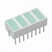
LED LT BAR 8.89X3.81MM QUAD GRN
Manufacturer
Avago Technologies US Inc.
Datasheet
1.HLMP-2500.pdf
(16 pages)
Specifications of HLMP-2820
Color
Green (x 8)
Voltage Rating
2.2V
Current
30mA
Lens Style/size
Rectangle, 8.89mm x 3.81mm
Configuration
4 Segment
Mounting Type
Through Hole
Product
LED Light Bars
Illumination Color
Green
Luminous Intensity
25 mcd
Light Bar Length
8.89 mm
Supply Voltage
2.2 V
Supply Current
20 mA
Wavelength
572 nm
Led Configuration
Bar
Led Color
4 Green
Forward Voltage
2.2V
Forward Current If
20mA
Leaded Process Compatible
Yes
Light Emitting Area
8.89 X 3.81
Rohs Compliant
Yes
Lead Free Status / RoHS Status
Lead free / RoHS Compliant
Lens Type
-
Lead Free Status / Rohs Status
Lead free / RoHS Compliant
Other names
516-1252-5
Available stocks
Company
Part Number
Manufacturer
Quantity
Price
Company:

Part Number:
HLMP-2820
Manufacturer:
AVAGO
Quantity:
40 000
Company:
Part Number:
HLMP-2820
Manufacturer:
Avago Technologies
Quantity:
135
Company:
Part Number:
HLMP-2820-FG000
Manufacturer:
AVAGO
Quantity:
40 000


Absolute Maximum Ratings
Notes:
1. Derate above 87 C at 1.7 mW/ C per LED chip. For DC operation, derate above 91 C at 0.8 mA/ C.
2. Derate above 25 C at 1.8 mW/ C per LED chip. For DC operation, derate above 50 C at 0.5 mA/ C.
3. Derate above 50 C at 1.8 mW/ C per LED chip. For DC operation, derate above 60 C at 0.5 mA/ C.
4. See Figure 1 to establish pulsed operation. Maximum pulse width is 1.5 mS.
5. See Figure 6 to establish pulsed operation. Maximum pulse width is 2 mS.
6. Does not apply to bicolor parts.
7. For operation below –20 C, contact your local Avago sales representative.
Electrical/Optical Characteristics at T
AlGaAs Red HLCP-X100 Series
6
Average Power Dissipated per LED Chip
Peak Forward Current per LED Chip
Average Forward Current per LED Chip
DC Forward Current per LED Chip
Reverse Voltage per LED Chip
Operating Temperature Range
Storage Temperature Range
Wave Soldering Temperature
1.6 mm (1/16 inch) below Body
Luminous Intensity
per Lighting Emitting
Area
Peak Wavelength
Dominant Wavelength
Forward Voltage per LED
Reverse Breakdown Voltage per LED
Thermal Resistance LED Junction-to-Pin
[1]
Parameter
Parameter
[2]
A100/D100/E100
B100/C100/F100/G100
H100
HLCP-
A
= 25 C
–20 C to +100 C
AlGaAs Red
HLCP-X100
37 mW
45 mA
15 mA
Series
15 mA
5 V
[4]
[1]
Symbol
[1]
R
PEAK
V
V
I
J-PIN
V
F
R
d
[7]
HLMP-2300/
2600/29XX
Min.
135 mW
12
90 mA
30 mA
3
6
5
Series
25 mA
250 C for 3 seconds
HER
–40 C to +85 C
–40 C to +85 C
[5]
[2]
Typ.
645
637
250
7.5
1.8
[2]
15
30
15
HLMP-2400/
Max.
2700/2950
2.2
85 mW
60 mA
25 mA
Yellow
Series
20 mA
6 V
[6]
Units
LED
mcd
mcd
mcd
C/W/
[5]
[3]
[3]
nm
nm
V
V
Test Conditions
–20 C to +85 C
HLMP-2500/
I
2800/2965
I
135 mW
R
I
F
90 mA
30 mA
F
Green
Series
= 100 A
25 mA
= 20 mA
= 3 mA
[5]
[2]
[2]
Related parts for HLMP-2820
Image
Part Number
Description
Manufacturer
Datasheet
Request
R

Part Number:
Description:
LED 3MM 569NM GREEN DIFF
Manufacturer:
Avago Technologies US Inc.
Datasheet:

Part Number:
Description:
LED 5MM 635NM HE RED WATER CLEAR
Manufacturer:
Avago Technologies US Inc.
Datasheet:

Part Number:
Description:
LED 5MM 639NM RED WATER CLEAR
Manufacturer:
Avago Technologies US Inc.
Datasheet:

Part Number:
Description:
LED LT BAR 8.89X3.81MM SGL GREEN
Manufacturer:
Avago Technologies US Inc.
Datasheet:

Part Number:
Description:
LED LT BAR 19.05X3.81MM SGL YLW
Manufacturer:
Avago Technologies US Inc.
Datasheet:

Part Number:
Description:
LED 3MM GAP DIFF GRN STRAIGHT TH
Manufacturer:
Avago Technologies US Inc.
Datasheet:

Part Number:
Description:
LED FLAT TOP GAP GRN CLEAR GW
Manufacturer:
Avago Technologies US Inc.
Datasheet:

Part Number:
Description:
LED 3MM GAP DIFF RED STR LDS
Manufacturer:
Avago Technologies US Inc.
Datasheet:

Part Number:
Description:
LED 3MM GAP DIFF RED STRAIGHT TH
Manufacturer:
Avago Technologies US Inc.
Datasheet:

Part Number:
Description:
LED 5MM FLAT TOP INGAN WHITE
Manufacturer:
Avago Technologies US Inc.
Datasheet:
Part Number:
Description:
LED 5MM FLAT TOP INGAN WHITE
Manufacturer:
Avago Technologies US Inc.
Datasheet:
Part Number:
Description:
LED 5MM FLAT TOP INGAN WHITE
Manufacturer:
Avago Technologies US Inc.
Datasheet:
Part Number:
Description:
LED 5MM FLAT TOP INGAN WHITE
Manufacturer:
Avago Technologies US Inc.
Datasheet:

Part Number:
Description:
LED DOME 565NM DIFF GRN GW
Manufacturer:
Avago Technologies US Inc.
Datasheet:

Part Number:
Description:
LED DOME 565NM DIFF GRN YOKE
Manufacturer:
Avago Technologies US Inc.
Datasheet: