3318G-1-103A Bourns Inc., 3318G-1-103A Datasheet
3318G-1-103A
Specifications of 3318G-1-103A


Related parts for 3318G-1-103A


3318G-1-103A Summary of contents
Page 1
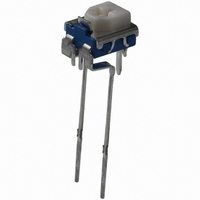
Electrical Characteristics Standard Resistance Range ............................................100 Ω MΩ (see standard resistance table) Resistance Tolerance .........................±20 % Contact Resistance Variation ..................................................10 % max. Resolution ..........................................Infinite Adjustment Angle........................210 °± 15 ° Environmental Characteristics Power Rating ...................................0.1 watt Temperature Range............-10 °C ...
Page 2
Square Trimming Potentiometer Product Dimensions Model 3318B 0.8 (.032) 6.5 3.5 (.256) (.138) 3.1 (.122) 104 DIA. 4.5 (.178) Mounting 3.5 Surface (.138 2.9 0.9 2 (.114) (.035) 0.5 + 0.1/-0 0.75 + 0.1/-0 ...
Page 3
... Ammo Pack Model 3318G 6.5 4.8 (.256) (.189) 3.35 3.1 2 (.123) (.122) DIA. 7.3 9.2 (.287) ( ...
Page 4
Square Trimming Potentiometer Packaging Specifications Ammo Pack Model 3318B 0.8 (.032) 6.3 3.5 (.248) 1.5 3.5 (.138) (.060) (.138) 2.0 4.8 (.079) (.189) 4.5 (.177) 3.5 (.138) 1 2.5 ± 0.5 2.3 (.098 ± .020) (.091) ...